Fault Code 29: Remote Throttle Enable
J1587: MID 130 SID 372 FMI 4, 5
J1939: SA 3 SPN 969 FMI 4, 5
Overview
The UltraShift PLUS transmission is equipped with a relay circuit that allows the throttle of the engine to be located in a remote location. The relay and associated wiring are installed by the OEM. Fault Code 29 sets when the Transmission Electronic Control Unit (TECU) detects an open or a shorted condition in the wiring between the TECU and the relay.
Detection
The TECU monitors the remote throttle enable circuit for opens or shorts. If either condition is present for 1 second or greater, the fault is set Active.
Conditions to Set Fault Code Active
FMI 4 – Voltage Below Normal or Shorted Low: TECU detects a short to ground in the circuit.
FMI 5 – Current Below Normal or Open Circuit: TECU detects an open circuit or excessive resistance in the circuit.
Fallback
Remote throttle will not function.
Conditions to Set Fault Code Inactive
All FMIs: Short or open condition is not detected by the TECU for 2 seconds.
Possible Causes
FMI 4, 5
- Vehicle Harness
- Bent, spread, loose or corroded terminals
- Wiring shorted to ground or open
- Remote Throttle Relay
- Internal failure
- TECU
- Internal failure
Component Identification
 |
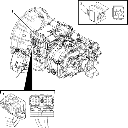
1. 38-Way Vehicle Harness Connector 2. Transmission Electronic Control Unit (TECU) 3. 5-Way Start Enable Relay Socket |
 |
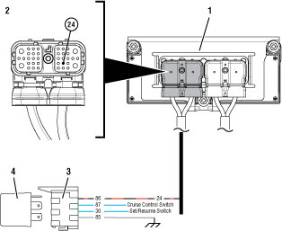
1. Transmission Electronic Control Unit (TECU) 2. 38-Way Vehicle Harness Connector 3. 5-Way Remote Throttle Enable Relay Socket 4. 5-Way Remote Throttle Enable Relay |
 |
Fault Code 29 Troubleshooting
Record the transmission fault codes, FMIs, occurrences, and timestamps from the Service Activity Report created during the Diagnostic Procedure.
If Fault Code 29 is Active, Go to Step C
If Fault Code 29 is Inactive and there are other Active fault codes, troubleshoot all Active fault codes first.
If Fault Code 29 is Inactive, Go to Step B
Set parking brake and chock wheels.
Place transmission in PD Mode. See more about Product Diagnostic (PD) Mode.
Note: Transmission does not enter PD Mode when Active fault codes exist.

Wiggle Vehicle Harness wiring and connections between TECU and Remote Throttle Relay.
Note: Wiring from the Remote Throttle Relay to TECU is OEM proprietary. Refer to OEM guidelines for proper repair or replacement procedures and proper wiring schematics and pin out locations.
Exit PD Mode by powering down.
Notice
If any fault became Active while wiggling wires in the system, refer to OEM guidelines for repair or replacement of wiring between TECU and Remote Throttle Relay. Go to Step V
If no fault codes became Active, Go to Step C
Key off.
Remove Remote Throttle Relay from socket.
Inspect Remote Throttle Relay Socket and wiring for damage or bent, spread, corroded or loose terminals.
If no issues are found, Go to Step D
If any issues are present, refer to OEM guidelines for repair or replacement of wiring of Remote Throttle Enable Relay circuit. Go to Step V
Key on with engine off.
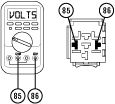
Measure voltage between Remote Throttle Relay socket Pin 86 (power) and Pin 85 (ground). Record reading(s) in table.

Compare reading(s) in table.
If readings are out of range, Go to Step E
If readings are in range, refer to OEM guidelines for replacement of the Remote Throttle Relay. Go to Step V
| Pins | Range | Reading(s) |
|---|---|---|
| 86 to 85 | Within 1.5 V of Battery Voltage |
Key off.
Disconnect 38-Way Vehicle Harness Connector from TECU.
Disconnect Remote Throttle Relay from socket.
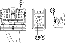
Measure resistance between 38-Way Connector Pin 24 and Relay Socket Pin 85. Record reading(s) in table.

Compare reading(s) in table.
If readings are in range, replace Transmission Electronic Control Unit (TECU). Go to Step V
If readings are out of range, repair or replace wiring between the 38-Way Vehicle Harness Connector and Remote Throttle Relay per OEM guidelines. Go to Step V
| Pins | Range | Reading(s) |
|---|---|---|
| 24 to 85 | 0–0.3 ohms |
Key off.
Reconnect all connectors and verify that all components are properly installed.
Key on with engine off.
Clear fault codes using ServiceRanger.
Drive vehicle and attempt to reset the code or duplicate the previous complaint.
Check for fault codes using ServiceRanger.
If no fault codes set Active and vehicle operates properly, test complete.
If Fault Code 29 sets Active during the test drive, Go to Step A
If a fault code other than 29 sets Active, troubleshoot per Fault Code Isolation Procedure Index.