Fault Code 35: J1939 Communication Link
J1587: MID 130 SID 231 FMI 2
J1939: SA 3 SPN 639 FMI 2
Overview
The J1939 Data Link is a Controller Area Network (CAN) communication bus. The UltraShift PLUS transmission uses the J1939 Data Link to communicate with other ECUs (ABS, Engine, Body Controller, etc.). The Transmission Electronic Control Unit (TECU) sends and receives messages from other ECUs on the data link to determine when to initiate a shift, hold shifts, command engine torque to make shifts, as well as other functions. Proper operation of the J1939 Data Link is critical for shift performance. Fault Code 35 indicates an issue with communication across the J1939 Data Link.
Detection
TECU has either lost communication or received erratic signals over the J1939 Data Link and the TECU has not detected any low battery system fault codes.
Conditions to Set Fault Code Active
FMI 2 – Data Erratic: TECU has lost communication or has received erratic signals over the J1939 Data Link for 5 seconds or longer.
Fallback
FMI 2
- “F” flashes in gear display.
- Service light flashes (if equipped).
- If vehicle is configured for the J1939 Start Enable feature the engine does not crank.
- If fault occurs during power up, the transmission requires the driver to manually synchronize shifts with the throttle.
- If fault occurs while driving, transmission remains in its current gear until the vehicle stops. Transmission then requires the driver to manually synchronize shifts with the throttle.
Conditions to Set Fault Code Inactive
FMI 2: TECU receives messages across the data link for at least 10 seconds.
Possible Causes
FMI 2
- 38-Way Vehicle Harness Connector
- Wiring shorted to ground, shorted to power or open
- Bent, spread, or loose terminals
- Other ECUs
- Internal failure
- J1939 Data Link
- Wiring shorted to ground, shorted to power or open
- Bent, spread, or loose terminals
- Excessive electrical noise
- Missing or additional terminating resistors
- TECU
- Internal failure
Component Identification
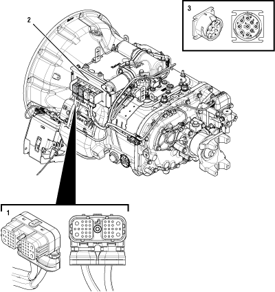 |
1. 38-Way Vehicle Harness Connector 2. Transmission Electronic Control Unit (TECU) 3. 9-Way Diagnostic Connector (in cab) |
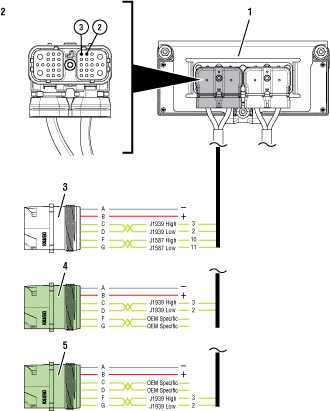 |
1. Transmission Electronic Control Unit (TECU) 2. 38-Way Vehicle Harness Connector 3. 9-Way Diagnostic Connector (Black) - OEM Specific CD (in cab) 4. 9-way Diagnostic Connector (Green) - OEM Specific CD (in cab) 5. 9-way Diagnostic Connector (Green) - OEM Specific FG (in cab) |
 |
Fault Code 35 Troubleshooting
Record the transmission fault codes, FMIs, occurrences, and timestamps from the Service Activity Report created during the Diagnostic Procedure.
If Fault Code 35 is Active, Go to Step C
If Fault Code 35 is Inactive, and there are other Active fault codes, troubleshoot all Active fault codes first per Fault Code Isolation Procedure Index.
If Fault Code 35 is Inactive, and there are no other Active fault codes, Go to Step B
Set parking brake and chock wheels.
Place transmission in PD Mode. See more about Product Diagnostic (PD) Mode.
Note: Transmission does not enter PD Mode when Active fault codes exist.

Wiggle J1939 Data Link wiring and Vehicle Harness wiring throughout the vehicle. Look for signs of pinched or chafed wiring. Verify all connections are clean and tight.
Exit PD Mode by powering down.
Note: Allow 2–3 minutes for the TECU to perform a complete power-down sequence before proceeding.
If Fault Code 35 or Fault Code 36 became Active while wiggling the J1939 Data Link or the Vehicle Harness, refer to OEM guidelines for repair or replacement of J1939 Data Link. Go to Step V
If no fault codes became Active, Go to Step C
Key off.
Refer to the OEM and identify the TECU location on the vehicle J1939 Data Link at the 9-Way Diagnostic Connector.
If Black 9-Way Diagnostic Connector, Go to Step D
If Green 9-Way Diagnostic Connector on Pin C and Pin D, Go to Step D
If Green 9-Way Diagnostic Connector on Pin F and Pin G, Go to Step H
Key off.
If vehicle is equipped with a Bulkhead Connection, inspect Bulkhead Connector for corrosion, loose terminals, and bent or spread pins.
Wiggle wiring connections to the Bulkhead Connector to verify the pins are not loose and are secure within the connector.
If no Bulkhead Connection is present, Go to Step E
If no damage is found and the connector is not loose, Go to Step E
If damage or looseness is found, refer to OEM guidelines for repair or replacement of Bulkhead Connection. Go to Step V
Key on with engine off.
Measure voltage between 9-Way Diagnostic Connector Pin C and Pin A. Record reading(s) in table.
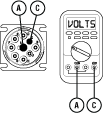
Measure voltage between 9-Way Diagnostic Connector Pin D and Pin A. Record reading(s) in table.
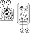
Record the total voltage in table by adding together the voltage readings recorded earlier in this step.
Compare reading(s) in table.
If readings are in range, Go to Step F
If readings are out of range, an issue is present on the vehicle J1939 Data Link. Refer to OEM guidelines for repair or replacement of the vehicle data link. Go to Step V
| Pins | Range | Reading(s) |
|---|---|---|
| C to A | N/A | |
| D to A | N/A | + |
| Total Voltage | 4.5–5.5 V | = |
Key off.
Note: Allow 2–3 minutes for the TECU to perform a complete power-down sequence before proceeding.
Measure resistance between 9-Way Diagnostic Connector Pin C and Pin D. Record reading(s) in table.
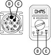
Compare reading(s) in table.
If readings are in range, Go to Step G
If readings are out of range, an issue is present on the vehicle J1939 Data Link. Refer to OEM guidelines for repair or replacement of terminating resistors, ECUs or data link wiring. Go to Step V
| Pins | Range | Reading(s) |
|---|---|---|
| C to D | 50–70 ohms |
Key off.
Disconnect 38-Way Vehicle Harness Connector from TECU.
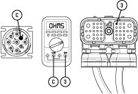
Measure resistance between 9-Way Diagnostic Connector Pin C and 38-Way Vehicle Harness Connector Pin 3. Record reading(s) in table.
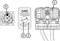
Measure resistance between 9-Way Diagnostic Connector Pin D and 38-Way Vehicle Harness Connector Pin 2. Record reading(s) in table.
Compare reading(s) in table.
If readings are in range, Go to Step L
If readings are out of range, refer to OEM guidelines for repair or replacement of vehicle J1939 Data Link. Go to Step V
| Pins | Range | Reading(s) |
|---|---|---|
| C to 3 | 0.0–0.3 ohms | |
| D to 2 | 0.0–0.3 ohms |
Key off.
If vehicle is equipped with a Bulkhead Connection, inspect Bulkhead Connector for corrosion, loose terminals, and bent or spread pins.
Wiggle wiring connections to the Bulkhead Connector to verify the pins are not loose and are secure within the connector.
If no Bulkhead Connection is present, Go to Step I
If no damage is found and the connector is not loose, Go to Step I
If damage or looseness is found, refer to OEM guidelines for repair or replacement of Bulkhead Connection. Go to Step V
Key on with engine off.
Measure voltage between 9-Way Diagnostic Connector Pin F and Pin A. Record reading(s) in table.
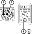
Measure voltage between 9-Way Diagnostic Connector Pin G and Pin A. Record reading(s) in table.
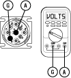
Record the total voltage in table by adding together the voltage readings recorded earlier in this step.
Compare reading(s) in table.
If readings are in range, Go to Step J
If readings are out of range, an issue is present on the vehicle J1939 Data Link. Refer to OEM guidelines for repair or replacement of the vehicle data link. Go to Step V
| Pins | Range | Reading(s) |
|---|---|---|
| F to A | N/A | |
| G to A | N/A | + |
| Total Voltage | 4.5–5.5 V | = |
Key off.
Note: Allow 2–3 minutes for the TECU to perform a complete power-down sequence before proceeding.
Measure resistance between 9-Way Diagnostic Connector Pin F and Pin G. Record reading(s) in table.
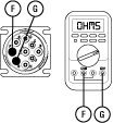
Compare reading(s) in table.
If readings are in range, Go to Step K
If readings are out of range, an issue is present on the J1939 Data Link. Refer to OEM guidelines for repair or replacement of terminating resistors, ECUs or data link wiring. Go to Step V
| Pins | Range | Reading(s) |
|---|---|---|
| F to G | 50–70 ohms |
Key off.
Disconnect 38-Way Vehicle Harness Connector from TECU.
Measure resistance between 9-Way Diagnostic Connector Pin F and 38-Way Vehicle Harness Connector Pin 3. Record reading(s) in table.
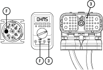
Measure resistance between 9-Way Diagnostic Connector Pin G and 38-Way Vehicle Harness Connector Pin 2. Record reading(s) in table.
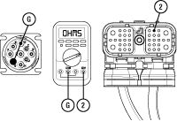
Compare reading(s) in table.
If readings are in range, Go to Step L
If readings are out of range, refer to OEM guidelines for repair or replacement of vehicle J1939 Data Link. Go to Step V
| Pins | Range | Reading(s) |
|---|---|---|
| F to 3 | 0.0–0.3 ohms | |
| G to 2 | 0.0–0.3 ohms |
Key off.
Reconnect all connectors and verify that all components are properly installed.
Connect ServiceRanger
Key on with engine off.
Retrieve and record the transmission fault codes and FMIs, and their occurrences and timestamps.
If Fault Code 35 is Inactive, an intermittent wiring issues exists within the vehicle J1939 Data Link, refer to OEM guidelines for repair or replacement of the data link. Go to Step V
If Fault Code 35 is Active, replace Transmission Electronic Control Unit (TECU). Go to Step V
Key off.
Reconnect all connectors and verify that all components are properly installed.
Key on with engine off.
Clear fault codes using ServiceRanger.
Drive vehicle and attempt to reset the code or duplicate the previous complaint.
Check for fault codes using ServiceRanger.
If no fault codes set Active and vehicle operates properly, test complete.
If Fault Code 35 sets Active during the test drive, Go to Step A
If a fault code other than 35 sets Active, troubleshoot per Fault Code Isolation Procedure Index.