Fault Code 41: Range Failed to Engage
J1587: MID 130 SID 35 FMI 7
MID 130 SID 36 FMI 7
J1939: SA 3 SPN 768 FMI 7
SA 3 SPN 769 FMI 7
Overview
Most Heavy-Duty UltraShift PLUS Transmission models are equipped with a 2-speed range system in the auxiliary case. The ability to select an auxiliary range gear independently from a main case gear allows the transmission twice the number of overall gear ratios. Main case gearing can be used once in auxiliary low range and again in auxiliary high range.
The range system is equipped with a Range Solenoid Valve. The Range Solenoid Valve is an electric-over-air solenoid controlled by the Transmission Electronic Control Unit (TECU), replacing the Shift Knob-Slave Valve system found on Eaton Cummins Automated Transmissions.
During operation, the solenoid directs air pressure to either port in the Range Cylinder based on the need to activate the auxiliary low range or high range gearing. The applied air pressure directs the fore-and-aft movement of the Range Piston within the Range Cylinder, facilitating the mechanical engagement of the Range Synchronizer into either low or high range. Fault Code 41 indicates the transmission is unable to complete a range shift.
Detection
When toggling the Range Solenoid Valve, the TECU verifies the new range position by calculating the overall transmission gear ratio, using the Main Shaft and Output Shaft Speed Sensor signals. If the calculated ratio does not match the expected ratio for the new range position, the auxiliary case gearing did not change as expected and the TECU sets the fault code Active.
The TECU detected a range system failure, but was unable to detect the specific root cause.
Conditions to Set Fault Code Active
FMI 7 – Mechanical System Not Responding: Transmission is either stuck in its current range position or it cannot engage the desired range position after five consecutive attempts.
Fallback
FMI 7
- Transmission remains in the range where the failure occurred.
- Transmission may attempt to shift into low range when the vehicle comes to a stop.
- Until the fault becomes Inactive, driver may have to shut off engine with transmission in gear.
Conditions to Set Fault Code Inactive
FMI 7: Transmission successfully attains the requested range for 2 seconds.
Possible Causes
FMI 7
- Vehicle Air System
- Low vehicle air pressure
- Contamination in air supply
- Air leaks
- Filter-Regulator failure
- Range Solenoid Valve
- Mechanical failure
- Mechanical Transmission
- Range Synchronizer failure
- Range Cylinder, Piston or Yoke wear or damage
- Range Cover Gasket failure
- Tone Wheel damage
- Failed auxiliary case components
- Main Shaft Speed Sensor
- Internal failure
- Output Shaft Sensor
- Internal failure
Additional Tools
- Two 0–100 PSI Air Pressure Gauges
- 0–150 PSI Air Pressure Gauge
Component Identification
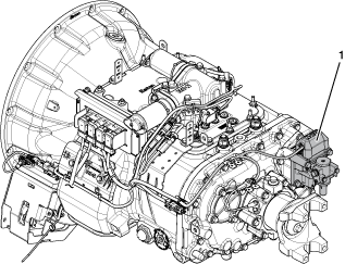 |
1. Range Solenoid Valve |
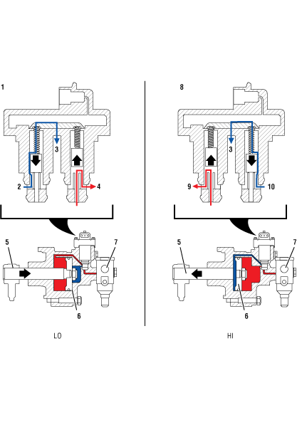 |
1. Range Solenoid Valve (LO) 2. Cylinder Port (Exhaust) 3. Exhaust Port 4. Regulated Port (Air) 5. Shift Yoke 6. Piston 7. Filter-Regulator 8. Range Solenoid Valve (HI) 9. Regulated Port (Air) 10. Cylinder Port (Exhaust) |
Fault Code 41 Troubleshooting
Record the transmission fault codes, FMIs, occurrences, and timestamps from the Service Activity Report created during the Diagnostic Procedure.
If Fault Code 41 FMI 7 is Active or Inactive, go to TAIB-0999 Fault Code 41 and/or 42 Due to a Restricted Range/Splitter Exhaust Port.
If Fault Code 41 FMI 7 is Active or Inactive, and Fault Codes 43, 57 or 58 are not set and Range Exhaust Port is not restricted, Go to Step B
Key off.
Set parking brake and chock wheels.
Vent vehicle air supply tanks.
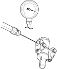
CautionInstall a 0–150 PSI air pressure gauge between the supply line and the air Filter-Regulator located at the back of the transmission.
Key on with engine running.
Allow air pressure to build to governor cut off.
Key off.
Monitor air pressure at gauge on supply line for 1 minute. Record reading(s) in table.
Compare reading(s) in table.
If readings are in range and the vehicle is able to maintain pressure, Go to Step C
If readings are out of range, or the vehicle can not hold pressure, repair vehicle air system per OEM guidelines. Go to Step V
| Model | Pressure | Reading(s) |
|---|---|---|
| All Models | 90–120 PSI |
Key off.
Vent vehicle air supply tanks.
CautionReconnect the supply line to the Air Filter-Regulator.
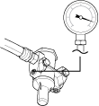
Install a 0–100 PSI air pressure gauge into a regulator test port of the Air Filter-Regulator.
Key on with engine running.
Allow air pressure to build to governor cut off.
Key off.
Monitor air pressure and record reading(s) in table.
Compare reading(s) in table.
If air pressure is in range, Go to Step D
If air pressure is out of range, replace Air Filter-Regulator. Go to Step V
| Model | Pressure | Reading(s) |
|---|---|---|
| All Models | 55–65 PSI |
Key off.
Vent vehicle air supply tanks.
CautionInstall a 0–100 PSI air pressure gauge into each of the range cover diagnostic ports (L and H).
Caution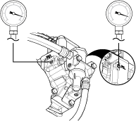
Key on with engine running.
Allow air pressure to build to governor cut off.
Key on with engine off.
CautionDepress Service Brake pedal and use the shift device to engage Reverse gear. Record air pressure reading of low-range pressure gauge in the table.
Note: Depress the Service Brake pedal and engage Reverse 1 (R1).
Depress the Service Brake pedal and use the shift device Upshift Button to engage the next Reverse gear. Record air pressure reading of high-range pressure gauge in table.
Note: Pressure change should be immediately reflected on the gauge.

Depress the Service Brake pedal and use the shift device to select Neutral. Verify that the transmission finds Neutral using the gear display.
Monitor air pressure and record reading(s) in table.
Compare reading(s) in table.
If readings are in range, Go to Step F
If readings are out of range or pressure is slow to change, Go to Step E
| Model | Pressure | Reading(s) |
|---|---|---|
| Low Range | 55-65 PSI | |
| High Range | 55-65 PSI |
Key off.
Vent vehicle air supply tanks.
CautionRemove Range Cylinder Cover.
Verify Range Cylinder Cover air ports are not obstructed or contaminated. Test for obstructions using shop air to ensure proper air flow.
If ports are obstructed or contaminated, replace Range Cylinder Cover, Range Valve and overhaul Range Cylinder. Go to Step G
If ports are not obstructed or contaminated, replace Range Valve and overhaul Range Cylinder. Go to Step G
Key off.
Vent vehicle air supply tanks.
CautionDisassemble Range Cylinder and components.
Inspect components for damage or contamination, specifically the Piston o-rings and Range Solenoid Valve.
Inspect Range Cylinder and ensure cylinder has a light coating of lube and is free from rust, corrosion or oil.
If components are in proper condition, Go to Step G
If components show signs of rust, corrosion or oil, or damage is found, overhaul Range Cylinder, replace Range Valve and resolve contamination issues with vehicle air system. Go to Step G
Note: Rust and moisture may cause premature failure in air system components.
Test drive vehicle and ensure that range system works as intended. Operate the vehicle in scenarios that require range shifts to be made.
If the vehicle does not properly complete range shifts, Go to Step H
If the vehicle completes range shifts without issues, Go to Step V
Inspect the Transmission Tone Wheel for damaged or missing gear teeth.
Drain transmission oil, looking for signs of significant metal fragments in the lubricant. Look for signs of internal damage to the transmission.
Remove auxiliary case from transmission.
Inspect auxiliary case Yoke Bar and Shift Yoke for any signs of damage.
Inspect Range Synchronizer for signs of worn friction material or broken Synchronizer Pins.
Ensure that auxiliary case Output Shaft Bearing and Auxiliary Countershaft Bearings are not damaged or worn.
If no damage is found, and the oil level is correct with no significant metal fragments, replace Range Valve. Go to Step V
If damage is found, repair or replace auxiliary case components as necessary. Go to Step V
Note: If the transmission is found to be low on oil, make sure to inspect the main case for damage due to the low lubricant condition.
Key off.
Reconnect all connectors and verify that all components are properly installed.
Key on with engine off.
Clear fault codes using ServiceRanger.
Drive vehicle and attempt to reset the code or duplicate the previous complaint.
Check for fault codes using ServiceRanger.
If no fault codes set Active and vehicle operates properly, test complete.
If Fault Code 41 sets Active during the test drive, Go to Step A
If a fault code other than 41 sets, troubleshoot per Fault Code Isolation Procedure Index.