Fault Code 58: Output Shaft Speed Sensor
J1587: MID 130 PID 191 FMI 2, 5, 6, 8, 10, 11
J1939: SA 3 SPN 191 FMI 2, 5, 6, 8, 10, 11
Overview
The UltraShift PLUS transmission is equipped with electronic speed sensors. The Input Shaft, Main Shaft and Output Shaft Speed Sensors are used to calculate gear ratios within the transmission. The Input Shaft Speed Sensor measures the rotational speed of the Input Shaft, taken from the upper countershaft drive gear. The Main Shaft Speed Sensor measures the rotational speed of the transmission gearing exiting the main case, taken from the auxiliary upper countershaft gear. The Output Shaft Speed Sensor measures the rotational speed and direction of the output shaft, taken from the Tone Wheel. The Transmission Electronic Control Unit (TECU) compares these speeds to calculate the gear ratios of the main case, auxiliary case and overall transmission.
The Output Shaft Speed Sensor transmits a digital signal to the TECU based on the rotational speed of the Output Shaft Tone Wheel. The TECU compares Main Shaft Speed to Output Shaft Speed to confirm the gear ratio of the auxiliary case and compares Input Shaft Speed to Output Shaft Speed to confirm the overall transmission gear ratio.
Fault Code 58 indicates an electrical fault within the Output Shaft Speed Sensor circuit or a speed value or rotational direction that is inconsistent with the calculated gear ratios.
Detection
The TECU compares the values of the three speed sensors to determine sensor validity. The TECU also monitors the Output Shaft Speed Sensor circuit for any shorts to power, shorts to ground, open circuits or incorrect rotational direction of the Output Shaft.
Conditions to Set Fault Code Active
The system can detect Output Shaft Speed Sensor faults when one of the following conditions is present for 1 second or longer:
FMI 2 – Data Erratic: TECU detects data from the Output Shaft Speed Sensor does not match the current gear ratio.
FMI 5 – Current Below Normal or Open Circuit: TECU detects an open circuit or the Output Shaft Speed Sensor has high resistance.
FMI 6 – Current Above Normal or Grounded Circuit: TECU detects a short to power in the circuit.
FMI 8 – Abnormal Frequency: TECU detects an incorrect rotational direction from the Output Shaft Speed Sensor.
FMI 10 – Abnormal Rate of Change: TECU detects an excessive rate change.
FMI 11 – Root Cause Unknown: TECU detects a speed sensor error.
Fallback
All FMIs
- “F” flashes in gear display.
- Service light flashes (if equipped).
- If fault occurs in low range, transmission still shifts up and down within low range, but will not complete the shift to high range.
- If fault occurs while in high range, the transmission still shifts up and down within high range. Once low range is reached, the transmission will not complete the shift back to high range.
Conditions to Set Fault Code Inactive
All FMIs: TECU receives a valid signal from the Output Shaft Speed Sensor and detects no electrical open or short circuits for 2 seconds.
Possible Causes
FMI 2
- Output Shaft Speed Sensor
- Internal failure
- Physical damage
- Mechanical Transmission
- Internal failure in auxiliary case
- Loose or broken Tone Wheel
FMI 5
- Output Shaft Speed Sensor
- Internal failure
- Physical damage or failure
- Transmission Harness
- Bent, spread, corroded or loose terminals
- Wiring shorted to ground, shorted to power or open
FMI 6, 8, 11
- Output Shaft Speed Sensor
- Internal failure
- Physical damage or failure
FMI 10
- Output Shaft Speed Sensor
- Internal failure
- Physical damage or failure
- Transmission Harness
- Bent, spread, loose or corroded terminals
- Wiring shorted to ground, shorted to power or open
- TECU
- Internal failure
- Mechanical Transmission
- Auxiliary Case: internal failure
- Tone Wheel loose or broken
Component Identification
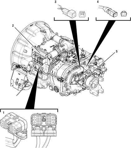 |
1. 38-Way Transmission Harness Connector 2. Transmission Electronic Control Unit (TECU) 3. 2-Way Output Shaft Speed Sensor Connector Body 4. 2-Way Output Shaft Speed Sensor Connector 5. 2-Way Output Shaft Speed Sensor |
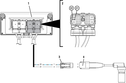 |
1. Transmission Electronic Control Unit (TECU) 2. 38-Way Transmission Harness Connector 3. 2-Way Output Shaft Speed Sensor Connector 4. 2-Way Output Shaft Speed Sensor |
 |
Fault Code 58 Troubleshooting
Record the transmission fault codes, FMIs, occurrences, and timestamps from the Service Activity Report created during the Diagnostic Procedure.
If Fault Code 58 FMI 5, 6 or 10 is Inactive, Go to Step B
If Fault Code 58 FMI 5, 6, 10 is Active, Go to Step F
If Fault Code 58 FMI 2 is Active or Inactive, Go to Step D
If Fault Code 58 FMI 8, 11 is Active or Inactive, Go to Step I
Set parking brake and chock wheels.
Place transmission in PD Mode. See more about Product Diagnostic (PD) Mode.
Note: Transmission does not enter PD Mode when Active fault codes exist.

Wiggle wiring and connections of the Transmission Harness from the Output Shaft Speed Sensor to the TECU. Look for signs of pinched or chafed wiring. Verify all connections are clean and tight.
Exit PD Mode by powering down.
Notice
If any fault code set Active while wiggling the Transmission Harness, replace Transmission Harness. Go to Step V
If no fault codes set Active, Go to Step C
Key off.
Set parking brake and chock wheels.
Attempt to move the Output Yoke at the rear of the transmission both vertically and horizontally. Look and feel for any play.
Verify that Tone Wheel is clean, free of debris or damage and does not spin freely by hand.
Remove Output Shaft Speed Sensor and inspect for any damage or signs of wear (cracks, broken pickup, etc.).
If play is present in Output Shaft End Yoke, Go to Step E
If Output Shaft Speed Sensor is damaged, replace Output Shaft Speed SensorD. Go to Step V
If no play is present and no damage found, Go to Step F
Key off.
Set parking brake and chock wheels.
Attempt to move the Output Yoke at the rear of the transmission both vertically and horizontally. Look and feel for any play.
Verify that Tone Wheel is clean, free of debris or damage and does not spin freely by hand.
Remove Output Shaft Speed Sensor and inspect for any damage or signs of wear (cracks, broken pickup, etc.).
If play is present in Output Shaft End Yoke, Go to Step E
If no play is present, replace Output Shaft Speed SensorD. Go to Step V
Drain transmission of lubricant into a clean pan for re-use. Note how much lubricant comes out and if significant metal fragments appear in the oil.
Remove the auxiliary case of the transmission and inspect for signs of damage, specifically inspecting the Auxiliary Output Bearing for signs of failure.
Inspect Output Shaft Bearing for any damage or wear.
If metal fragments are found, or if damage is found in the auxiliary case, repair or replace auxiliary case components as necessary. Go to Step V
If no metal fragments are found, replace Auxiliary Output Bearing and reinstall auxiliary case. Go to Step V
Key on with engine off.
Disconnect 2-Way Output Shaft Speed Sensor.
Inspect 2-Way Connector body for damage and bent, spread, corroded or loose terminals.
Inspect 2-Way Connector and Transmission Harness for any signs of cut, chafed or damaged wiring.
Measure voltage between the 2-Way Output Shaft Speed Sensor Connector Pin 1 and ground.

Compare reading(s) in table.
If readings are in range, Go to Step H
If readings are out of range, Go to Step G
| Pins | Range | Reading(s) |
|---|---|---|
| 1 to Ground | 4.5–6.0 V |
Key off.
Disconnect 38-Way Transmission Harness Connector from the TECU.
Inspect 38-Way Connector body for damage and bent, spread, corroded or loose terminals.
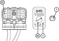
Measure resistance between 38-Way Transmission Harness Connector Pin 22 and 2-Way Output Shaft Speed Sensor Connector Pin 1. Record reading(s) in table.
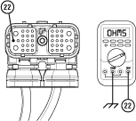
Measure resistance between 38-Way Transmission Harness Connector Pin 22 and ground. Record reading(s) in table.
Compare reading(s) in table.
If readings are in range, replace Output Shaft Speed SensorD and Transmission Harness. Go to Step V
If readings are out of range, replace Transmission Harness. Go to Step V
| Pins | Range | Reading(s) |
|---|---|---|
| 22 to 1 | 0.0–0.3 Ohms | |
| 22 to Ground | Open Circuit (OL) |
Key off.
Disconnect 38-Way Transmission Harness Connector at TECU.
Inspect 38-Way Connector body for damage and bent, spread, corroded or loose terminals.
Measure resistance between 38-Way Transmission Harness Connector Pin 21 and 2-Way Output Shaft Speed Sensor Connector Pin 2.
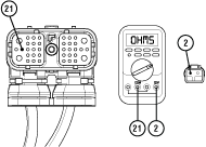
Compare reading(s) in table.
If readings are in range, replace DOutput Shaft Speed Sensor. Go to Step V
If readings are out of range, replace Transmission Harness. Go to Step V
| Pins | Range | Reading(s) |
|---|---|---|
| 21 to 2 | 0.0–0.3 ohms |
Set parking brake and chock wheels.
Key off.
Disconnect the 2-Way Output Speed Sensor.
Inspect the 2-Way Output Speed Sensor Connector, verify the connector is free from contamination and corrosion; the terminals are not bent, spread or loose; and there is no damage to the connector body.
Inspect the Transmission Harness side of the 2-Way Output Speed Sensor Connector, verify the connector is free from contamination and corrosion; the terminals are not bent, spread or loose; and there is no damage to the connector body.
If no contamination and damage is found, replace the DOutput Shaft Speed Sensor. Go to Step V
If contamination or damage is found, replace the DOutput Shaft Speed Sensor and Transmission Harness. Go to Step V
Key off.
Reconnect all connectors and verify that all components are properly installed.
Key on with engine off.
Clear fault codes using ServiceRanger.
Drive vehicle and attempt to reset the code or duplicate the previous complaint.
Check for fault codes using ServiceRanger.
If no fault codes set and vehicle operates properly, test complete.
If Fault Code 58 sets Active during the test drive, Go to Step A
If a fault code other than 58 sets, troubleshoot per Fault Code Isolation Procedure Index.