Fault Code 64: Gen1 Electronic Clutch Actuator (ECA)
J1587: MID 130 PID 34 FMI 2, 7, 12
J1939: SA 3 SPN 788 FMI 2, 7, 12
Overview
The UltraShift PLUS transmission is equipped with an Electronic Clutch Actuator (ECA) that controls the position of the clutch assembly. Power and ground to the ECA are OEM-supplied through a 3-Way Gen1 ECA Connector directly connected to the vehicle batteries. The ECA is connected to the TECU by an 8-Way Gen1 ECA Connector that is part of the transmission harness. The ECA communicates with the TECU over the High Integrity Link (HIL) to change position, show faults or include other operation information.
Detection
The TECU monitors the ECA for excessive motor current, excessive motor temperature, incorrect motor position, improper battery or ignition voltage to the ECA, or various internal ECA malfunctions.
Conditions to Set Fault Code Active
FMI 2 – Data Erratic: ECA detects a loss of battery and/or ground for 1 second or longer.
FMI 7 – Mechanical System Not Responding: ECA detects excessive motor current or ECA detects incorrect clutch position during a clutch position change for 1 second or longer.
FMI 12 – Bad Intelligent Device: ECA detects an internal failure for 1 second or longer.
Fallback
All FMIs
- “F” flashes in gear display.
- Service light flashes (if equipped).
- If the fault occurs at power up, engine cranks and starts, but TECU will not engage a gear.
- If the fault occurs while driving, ECA maintains current clutch position or moves to the last position commanded by the TECU. Transmission may continue to shift until vehicle is stopped.
Conditions to Set Fault Code Inactive
FMI 2: No loss of battery and ground is detected for 2 seconds.
FMI 7: Normal motor current is detected and ECA position is correct for 2 seconds.
FMI 12: No internal ECA failures are detected for 2 seconds.
Possible Causes
FMI 2, 12
- ECA Power Harness
- Bent, spread, corroded or loose terminals
- Wiring shorted to ground, shorted to power or open
- ECA
- Internal failure
FMI 7
- ECA Power Harness
- Bent, spread corroded or loose terminals
- Wiring shorted to ground, shorted to power or open
- Mechanical Clutch System
- Lack of lubrication of clutch release shaft/bushings
- Lack of lubrication of clutch
- Damage to clutch release yoke or cross shaft
- Internal failure
- ECA
- Internal failure
- TECU
- Software issue
- Vehicle Harness
- Wiring shorted to ground or shorted to power
Component Identification
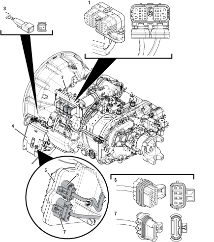 |
1. 38-Way Transmission Harness Connector 2. Transmission Electronic Control Unit (TECU) 3. 2-Way Terminating Resistor Connector Body 4. Gen1 ECA Shield 5. Gen1 Electronic Clutch Actuator (ECA) 6. 8-Way Gen1 ECA Connector 7. 3-Way Gen1 ECA Connector |
 |
Eaton ECA Clutch 1. Clutch Wear Tab 2. Release Bearing 3. Release Bearing Grease Zerk |
Fault Code 64 Troubleshooting Gen1 ECA
Inspect ECA OEM Power Supply Connector, reference image below.
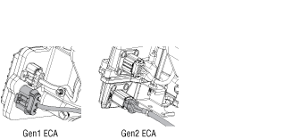
If equipped with a Gen1 ECA, Go to Step B
If equipped with a Gen2 ECA, go to Fault Code 64: Gen2 Electronic Clutch Actuator (ECA).
Record the transmission fault codes, FMIs, occurrences, and timestamps from the Service Activity Report created during the Diagnostic Procedure.
If Fault Code 64 is Inactive and there are other Active fault codes, troubleshoot all Active fault codes per Fault Code Isolation Procedure Index.
If Fault Code 64 FMI 7 is Active and the ECA was just reinstalled or replaced, go to TAIB-0996 Fault Code 27 FMI 7 and/or 64 FMI 7 Set Active After ECA Installation.
If Fault Codes 15, 16 or 19 is Active, troubleshoot per Fault Code Isolation Procedure Index.
If Fault Code 64, FMI 12 is set, Go to Step C
If Fault Code 64, FMI 7 is set, Go to Step L
Key off.
Set parking brake and chock wheels.
Load test each vehicle battery per OEM specifications. Record reading(s).
If any battery does not pass the Load Test, refer to OEM guidelines for repair or replacement of batteries. Go to Step V
If all batteries pass the Load Test, Go to Step D
| Battery | Voltage Drop | Load Test Status (Pass/Fail) |
|---|---|---|
| 1 | ||
| 2 | ||
| 3 | ||
| 4 | ||
| 5 |
Key off.
Inspect the ECA Power Supply Harness between the batteries and the ECA for signs of rubbing or chafing to the wiring.
Inspect the ECA 40-amp In-line Fusible Link or Fuse Holder Connections for damage and bent, spread, corroded or loose terminals.
Note: Some chassis use a power and ground distri-bution block separate from the battery or may route power and ground to the starter. Be sure to clean and inspect connections at this location and at the battery.
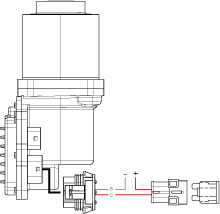
If damage to the ECA Power Supply Harness is found, refer to OEM guidelines for repair or replacement. Go to Step V
If no damage is found, Go to Step E
Key off.
Disconnect 3-Way Gen1 ECA Connector.
Verify connector is free from any corrosion; the terminals are not bent, spread or loose; and there is no damage to the connector body.
Confirm the 3-Way Gen1 ECA Connector has a seal plug in Cavity A.
Inspect ECA side of 3-Way Gen1 ECA Connector, verify connector is free from any corrosion, the terminals are not bent, spread or loose; and there is no damage to the connector body.
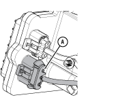
If damage to the 3-Way Gen1 ECA Connector is found and/or missing seal plug in Cavity A, refer to OEM guidelines for repair or replace-ment. Go to Step V
If damage to the ECA side of 3-Way Gen1 ECA Connector is found, replace Electronic Clutch Actuator (ECA). Go to Step V
If no damage is found, Go to Step F
Key off.
Measure voltage between 3-Way Gen1 ECA Connector Pin C (Battery positive) and Pin B (Battery negative). Record reading(s) in table.
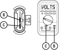
Compare reading(s) in table.
If readings are out of range, refer to OEM guidelines for repair or replacement of the ECA Power Supply Harness. Go to Step V
If readings are in range, Go to Step G
| Pins | Range | Reading(s) |
|---|---|---|
| C to B | Within 1.2 V of Battery Positive (+) |
Key off.
Measure voltage between 3-Way Gen1 ECA Connector Pin C (Battery positive) and ground. Record reading(s) in table.
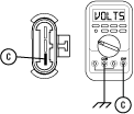
Compare reading(s) in table.
If readings are out of range, Pin C (Battery positive) and Pin B (Battery negative) wires are incorrectly pinned in the 3-Way Gen1 ECA Connector. Refer to OEM requirements for repair or replacement. Go to Step V
If readings are in range, Go to Step H
| Pins | Range | Reading(s) |
|---|---|---|
| C to Ground | Within 1.2 V of Battery Positive (+) |
Key off.
Load test the 3-Way Gen1 ECA Connector and ECA Power Supply Harness with an external load source. Use a sealed beam headlamp or blower motor attached to Pin C (Battery positive) and Pin B (Battery negative). Load Test for 5 minutes to verify the harness will carry a load with the 40-amp fuse or fusible link installed.

Wiggle the ECA Power Supply Harness during the Load Test from the vehicle batteries to ECA.
If the ECA Power Supply Harness does not carry a load, refer to OEM guidelines for repair or replacement. Go to Step V
If the ECA Power Supply Harness carries a load, Go to Step I
Determine which FMI set for Fault Code 64, as noted in Step B.
If FMI 2 or 12 set and no fault was found with the ECA Power Supply Harness or battery/charging system, replace the Electronic Clutch Actuator (ECA). Go to Step V
If FMI 7 set, Go to Step J
Key off.
NoticeSet parking brake and chock wheels.
Remove single bolt for clutch housing access cover.
Inspect for excessive clutch dust, broken clutch or spring material or other signs of clutch failure.
Ensure Release Bearing and Cross Shaft are adequately greased per the Heavy-Duty Clutch Service Manual (CLSM0200).
If physical signs of a failure are present, replace Heavy-Duty ECA Clutch and Cross Shaft. Go to Step V
If no issues found and properly greased, Go to Step K
Key off.
Remove ECA.
Inspect Clutch Release Yoke for excessive wear.
Rotate Clutch Release Yoke and Cross Shaft. Verify that they rotate freely without binding.
If the Clutch Release Yoke shows excessive wear, replace Clutch Release Yoke. Go to Step V
If the Clutch Release Yoke and Cross Shaft bind when rotated, replace Cross Shaft. Go to Step V
If no issues are found with the Clutch Release Yoke and Cross Shaft rotates freely without binding, and no fault was found with the ECA Power Supply Harness or battery/charging system, replace the Electronic Clutch Actuator (ECA). Go to Step V
Determine if vehicle manufacturer is PACCAR.
If vehicle is not manufactured by PACCAR, Go to Step M
If vehicle is manufactured by PACCAR, Go to Step N
Key on with engine off.
Connect ServiceRanger.
Go To Programming.
Under "Software Information", record TECU software version.
If TECU software is less than 5570065, update TECU software to 5570065 or greater. Go to Step V
If TECU software is 5570065 or greater, Go to Step C
Key on with engine off.
Connect ServiceRanger.
Go To Programming.
Under "Software Information", record TECU software version.
If TECU software is less than 5570065, update TECU software to 5570065 or greater. Go to Step O
If TECU software is 5570065 or greater, Go to Step O
Refer to TAIB-0883.
If TAIB-0883 has not been completed, perform TAIB-0883.
If TECU software was updated during previous step and vehicle does not meet criteria of TAIB-0883 or if TAIB-0883 was already completed, Go to Step V
If TECU software was not updated during previous step and vehicle does not meet criteria of TAIB-0883 or if TAIB-0883 was already completed, Go to Step C
Key off.
Reconnect all connectors and verify that all components are properly installed.
Key on.
Clear fault codes using ServiceRanger.
Drive vehicle and attempt to reset the code or duplicate the previous complaint.
Check for fault codes using ServiceRanger:
If no codes set and the vehicle operates properly, test complete.
If Fault Code 64 sets active during the test drive, Go to Step A
If a fault code other than 64 sets, Fault Code Isolation Procedure Index.