Main Shaft End-Play Service Procedure
Special Instructions
Main Shaft End-Play must be measured and adjusted after Clutch Housing, Main Housing, Input Shaft, Input Shaft Bearing or Main Shaft Bearing replacement.
Special Tools
- Torque Wrench
- 4 Flat Washers (22.3 mm (0.9 in) minimum OD)
- Dial Indicator
- 2 Pry Bars
- 5/32 OD Air Line
- Front Bearing Capture Plate (RR1085TR-7)
- Plastic Scraper
- Non-Chlorinated Brake Cleaner (Gasket Remover)DangerCaution
Component Identification
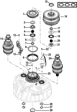 | ||
1. Primary Drive Gear 2. Spherical Washer - Front 3. Bearing Race - Front 4. Needle Bearing - Front 5. Thrust Bearing - Front 6. Thrust Washer - Front 7. Wave Spring - Front 8. Synchronizer Ring 9. Synchronizer Sliding Sleeve 10. Synchronizer Rollers (x3) | 11. Synchronizer Springs and Plungers (x3) 12. Lower Lube Tube Cap Screw - 8 mm 13. Lower Lube Tube 14. Upper Countershaft 15. Main Shaft Selective Washer - 6.525 mm (0.257 in), 6.712 mm (0.264 in) or 6.900 mm (0.272 in) (x1) 16. Main Shaft Assembly 17. Wave Spring - Rear 18. Thrust Washer - Rear | 19. Thrust Bearing - Rear 20. Needle Bearing - Rear 21. Bearing Race - Rear 22. Upper Lube Tube Cap Screw - 8 mm 23. Upper Lube Tube 24, Lower Countershaft 25. Input Shaft Assembly 26. Countershaft Flat Washers (x2) 27. Countershaft Snap Rings (x2) 28. Input Shaft Snap Ring |
Verify Components in the Clutch Housing
Verify Input Shaft Bearing is fully seated in Clutch Housing to ensure a proper Main Shaft End-Play reading.
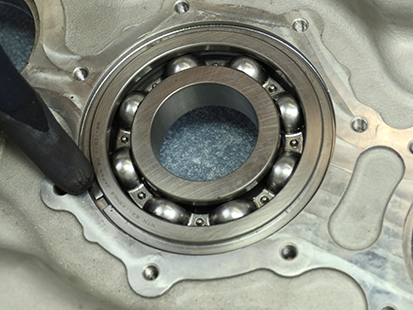
Ensure Input Shaft Snap Ring is installed as instructed in the Clutch Housing to verify that the Input Shaft is fully seated.
Remove Input Shaft Snap Ring and install Front Bearing Capture Plate (RR1085TR-7) and torque to 21-25 Nm (16-19 lb-ft).
Note: The Input Shaft Bearing must be fully seated against the bearing stop in the Clutch Housing to ensure a proper Main Shaft End-Play reading.
Place and support Clutch Housing on a bench.
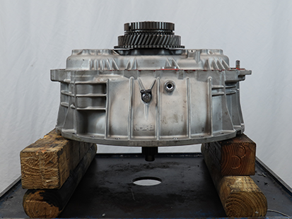
Install the Main Shaft and Countershaft
On the Secondary Drive Gear, apply paint marks on 2 gear teeth exactly 180-degrees across from each other, if not already marked.
Note: Paint marks are required for timing the Secondary Drive Gear to the Countershafts.
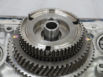
Install 3 springs and plungers into Synchronizer hub.
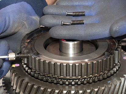
Install Rail B Synchronizer Sliding Sleeve with bevel facing up.
Notice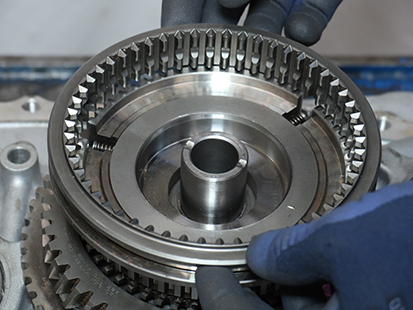
Lift and hold the Rail B Synchronizer Sliding Sleeve, install 3 rollers over the 3 springs and plungers and into the sliding sleeve groove.
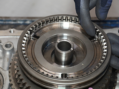
Slowly press down the Synchronizer Sliding Sleeve to the neutral position and seat the 3 rollers evenly on the springs and plungers.
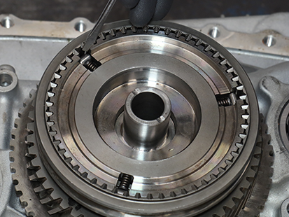
Install Rail B Synchronizer Ring.
Note: Align the 3 tabs on ring to the 3 openings on the hub at each spring and plunger.
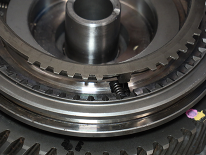
Install Wave Spring - Front.
Note: Wave Spring - Front is taller than the Wave Spring - Rear.
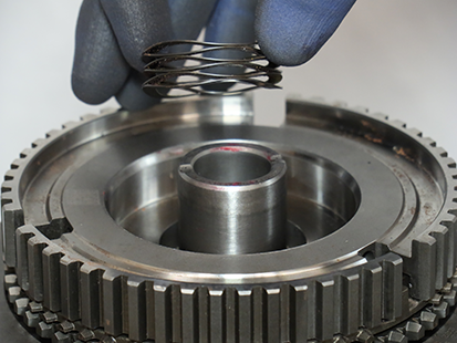
Install Thrust Washer - Front.
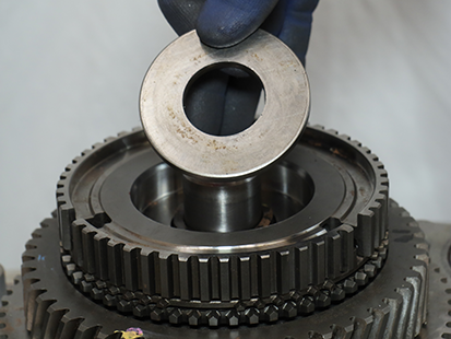
Install Needle Bearing - Front.
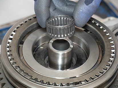
Install Thrust Bearing - Front.
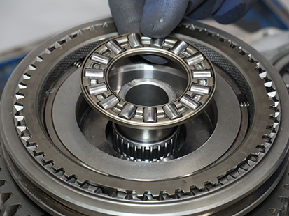
Install Bearing Race - Front.
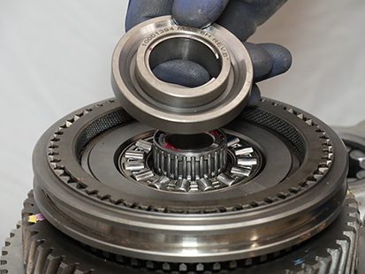
Install Spherical Washer - Front with conical side down.
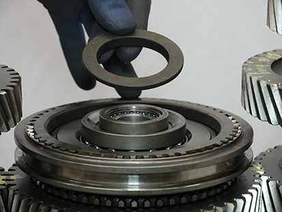
Install Lower Countershaft Pilot Tool (RR1071TR) to front section of Lower Countershaft.
Note: Lower Countershaft has Inertia Brake Splines on the front and Oil Pump drive slot on the rear.
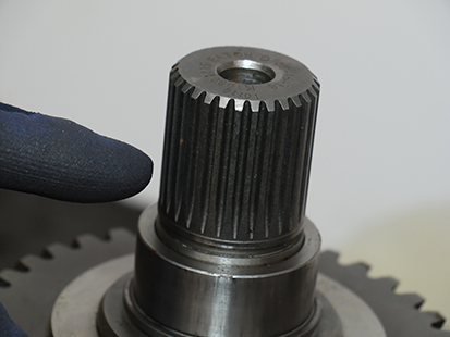
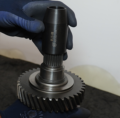
On the Lower Countershaft front drive gear, apply paint marks on the 2 gear teeth marked “0 0".
NoticeNote: Paint marks are required for timing the Secondary Drive Gear to the Countershafts.
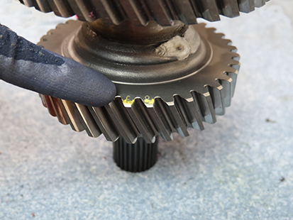
Install Lower Countershaft with Countershaft Pilot Tool (RR1071TR). Ensure timing marks align with Secondary Drive Gear and Lower Countershaft front drive gear.
Caution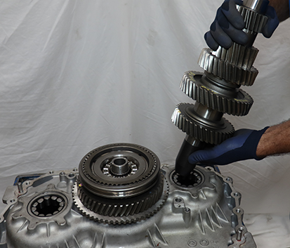
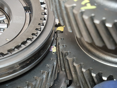
Install Upper Countershaft Pilot Tool (RR1072TR) to front section of Upper Countershaft.
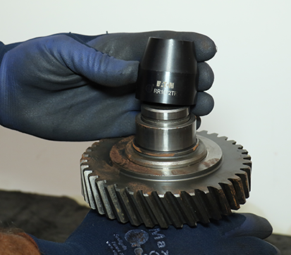
On the Upper Countershaft front drive gear, apply paint marks on the 2 gear teeth marked “0 0".
NoticeNote: Paint marks are required for timing the Secondary Drive Gear to the Countershafts.

Install Upper Countershaft with Upper Countershaft Pilot Tool (RR1072TR) into bearing. Ensure timing marks align with Secondary Drive Gear and Upper Countershaft front drive gear.
Caution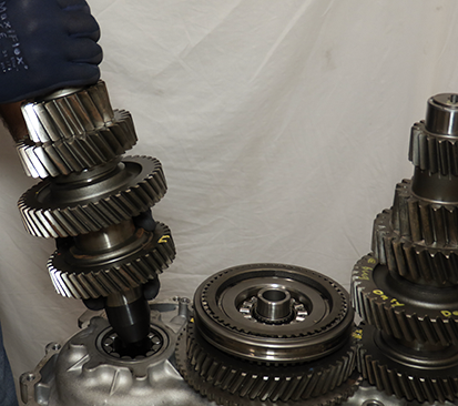
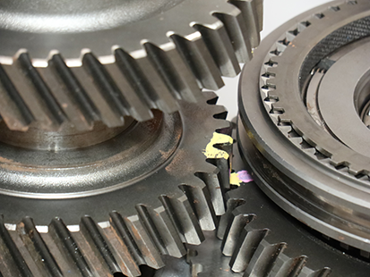
Install Primary Drive Gear with clutching teeth facing up onto Rail B Synchronizer.
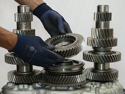
Install Bearing Race - Rear.
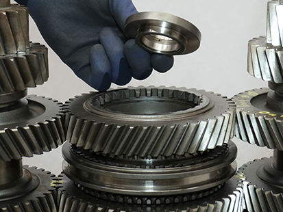
Install Needle Bearing - Rear.
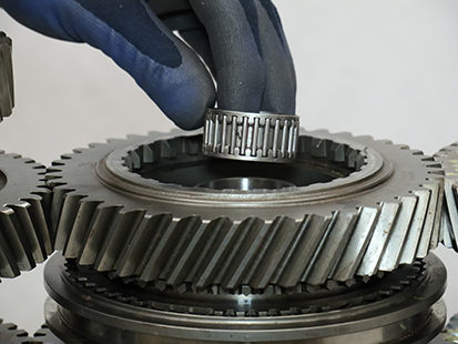
Install Thrust Bearing - Rear.
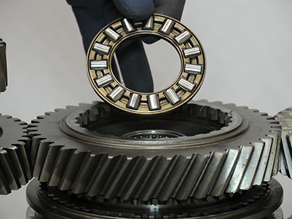
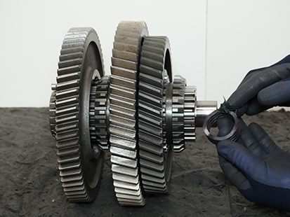
Apply transmission assembly lube to Wave Spring - Rear and install to Main Shaft.
NoticeNote: Transmission assembly lube holds Wave Spring - Rear in place during Main Shaft Assembly installation.
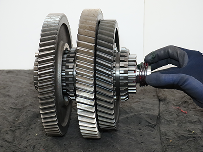
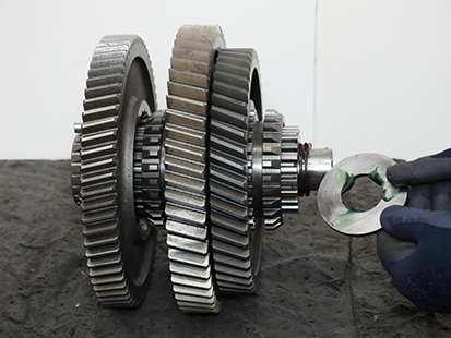
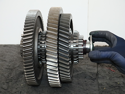
Apply transmission assembly lube to Thrust Washer - Rear and install to Main Shaft.
Note: Transmission assembly lube holds Thrust Washer - Rear in place during Main Shaft Assembly installation.
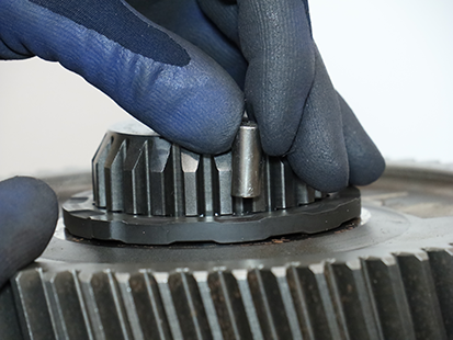
Install a magnet onto the Main Shaft Key.
Note: The magnet holds the key in position during Main Shaft Assembly installation.
Slide and hold Rail C Sliding Clutch into Secondary Driven Gear.
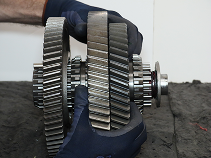
Install Main Shaft Assembly onto Primary Drive Gear and align gearing.
Caution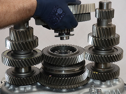
Remove magnet from Main Shaft Key.
Notice
Install Upper Lube Tube into Clutch Housing and install 8 mm cap screw and torque to 8–10 Nm (6–13 lb–ft).
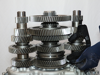
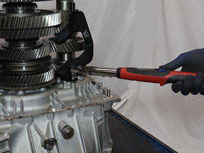
Install Lower Lube Tube into Clutch Housing and 8 mm cap screw, torque to 8–10 Nm (6–13 lb–ft).
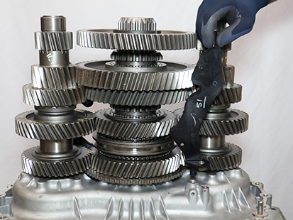
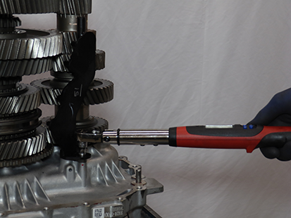
If Clutch Housing, Main Housing, Input Shaft, Input Shaft Bearing or Main Shaft Bearing has been replaced, perform steps to Install the Main Housing without Gasket Sealant before measuring and adjusting Main Shaft End-Play. If these parts have NOT been replaced, perform Install Main Housing .
Install the Main Housing without Gasket Sealant
Clean the sealing surfaces on the Clutch Housing and Main Housing with gasket remover and a plastic scraper. Let air dry then wipe with a clean dry cloth.
NoticeInspect threaded bolt holes for debris and clean if necessary.
NoticeSlide O-ring over the Clutch Housing Inertia Brake air passage alignment pin until fully seated in groove.
Notice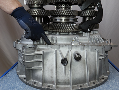
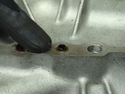
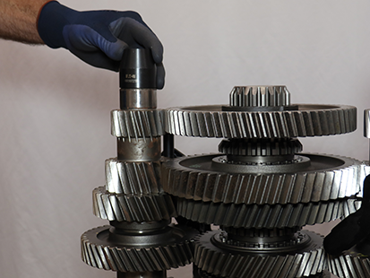
Install Lower Countershaft Pilot Tool (RR1071TR) onto Lower Countershaft above rear bearing race.
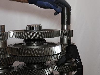
Install Upper Countershaft Pilot Tool (RR1072TR) onto the Upper Countershaft above rear bearing race.
Install and hand tighten 2 Rear Housing 90-degree Lifting Eyes and 15 mm cap screws to Main Housing.
NoticeNote: Install 90-degree Lifting Eyes 180-degrees apart to ensure even lifting.
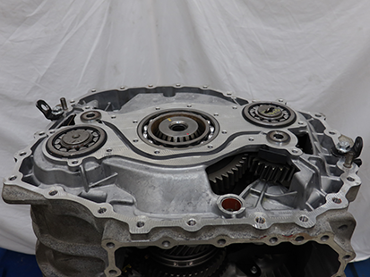
Install and hand tighten 2 Rear Housing Alignment Pins (RR1090TR) into the Clutch Housing as shown below.
Lift, align and install Main Housing to Clutch Housing.
CautionNoticeNote: Using a flat tipped screwdriver, rotate the Reverse Idler Gears to align the gearing and allow Main Housing to fully seat onto the Clutch Housing.
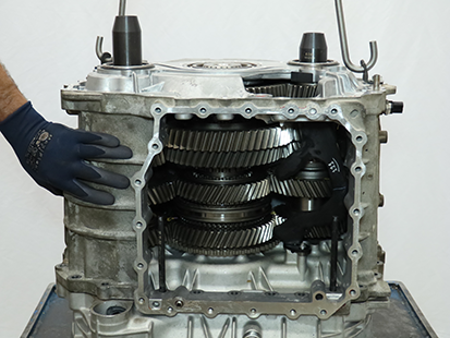
Remove 2 Rear Housing Alignment Pins (RR1090TR).
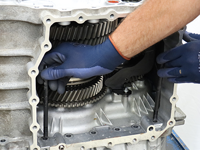
Install 19 external and 6 internal Main Housing 16 mm cap screws and torque to 44–51 Nm (33–38 lb–ft) in a criss-cross pattern.
Notice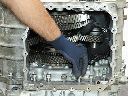
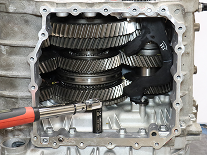
Measure and Adjust the Main Shaft End-Play
Note: The Main Shaft Selective Washer is available in 3 thicknesses: 6.525 mm (0.257 in), 6.712 mm (0.264 in) or 6.900 mm (0.272 in).
Install 4 Oil Pump 13 mm cap screws with flat washers (22.3 mm (0.9 in) minimum OD). Torque cap screws to 21-23 Nm (16-18 lb-ft).
Note: Flat washers are required to ensure the Main Shaft Bearing remains seated in the Main Housing during End-Play measurement.
Thread a Dial Indicator mounting shaft into one of the inner Oil Pump mounting holes around the Main Shaft Bearing.
Note: The Oil Pump cap screw mounting holes thread pattern: M8 x 1.25 x 30 mm.
Mount the Dial Indicator to the shaft, set the plunger on the Main Shaft, and zero the Dial Indicator.
Note: Ensure that the Dial Indicator is vertical and zeroed for proper Main Shaft End-Play measurement.
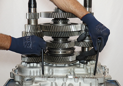
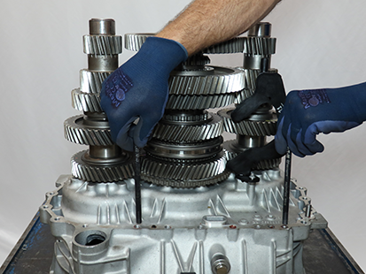
Use two pry bars and slide them between the Reverse Gear and Main Housing at the locations shown below.
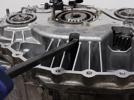
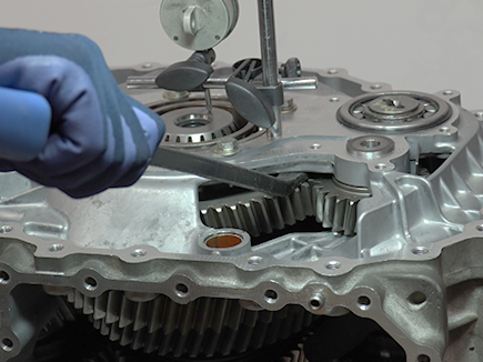
Apply even downward pressure on Reverse Gear with both pry bars and monitor the Dial Indicator between the at-rest position of the Main Shaft and the point where no more downward movement is achieved. Record reading in table.
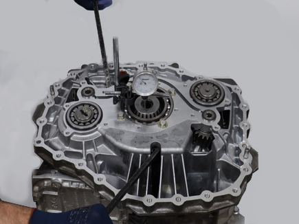
Reference the Selective Main Shaft Washer Reference Chart and compare Recorded End-Play to reading in table.
Note: Main Shaft End-Play specification is 0.000-0.100 mm (0.000-0.004 in). The Selective Washer Chart is only valid for end-play measured with the 6.525 mm (0.257 in) selective washer installed.
- If end-play is in range, the installed Main Shaft Selective Washer, 6.525 mm (0.257 in), is correct.
- If end-play is out of range, determine the thicker ideal Main Shaft Selective Washer and record in table. Remove Main Shaft and install the Ideal Main Shaft Selective Washer.
Caution
Remove Main Housing
Remove the 19 external and 6 internal Main Housing 16 mm cap screws.
Notice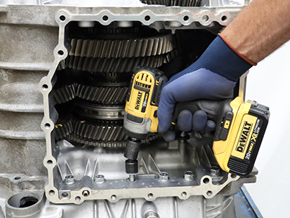
Install and hand tighten 2 Rear Housing Alignment Pins (RR1090TR) in the internal Main Housing cap screw outer threaded holes.
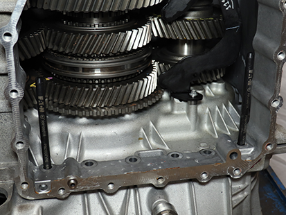
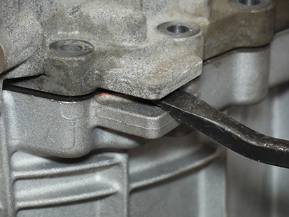
Separate Main Housing from Clutch Housing at the 2 pry points.
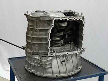
Lift and remove Main Housing from Clutch Housing.
CautionNotice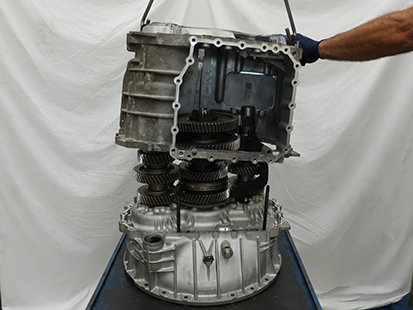
Remove 2 Rear Housing Alignment Pins (RR1090TR).
Note: Applying sealer when installing Main Housing to Clutch Housing should only be done after proper Main Shaft End-Play has been verified.
Reference the Selective Main Shaft Washer Reference Chart and compare Recorded End-Play to reading in table.
Note: Main Shaft End-Play specification is 0.000-0.100 mm (0.000-0.004 in). The Selective Washer Chart is only valid for end-play measured with the 6.525 mm (0.257 in) selective washer installed.
- If end-play is in range, the installed Main Shaft Selective Washer, 6.525 mm (0.257 in), is correct.
- If end-play is out of range, determine the thicker Ideal Main Shaft Selective Washer and record in table. Remove Main Shaft and install the Ideal Main Shaft Selective Washer.
Caution
Remove Main Shaft and Countershaft
Remove the Upper Lube Tube 8 mm cap screw.
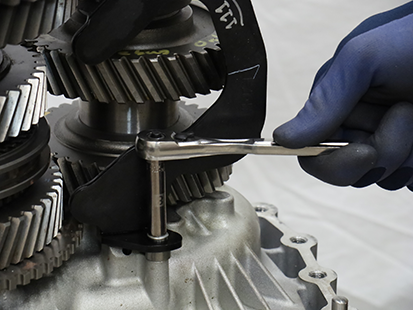
Remove the Upper Lube Tube.
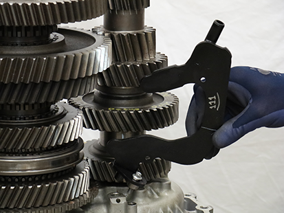
Remove the Lower Lube Tube 8 mm cap screw.
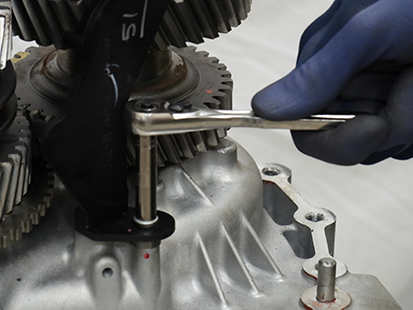
Remove the Lower Lube Tube.

Install a magnet onto Main Shaft Key to ensure the key stays in place during Main Shaft Removal and Installation.
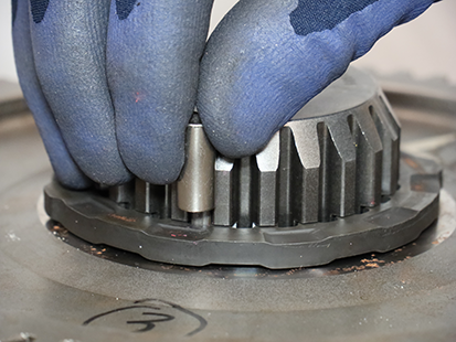
Hold Rail C Sliding Clutch against Secondary Driven Gear and lift Main Shaft from Primary Drive Gear.
CautionNote: Spring and Washer may remain attached to the Main Shaft during removal.
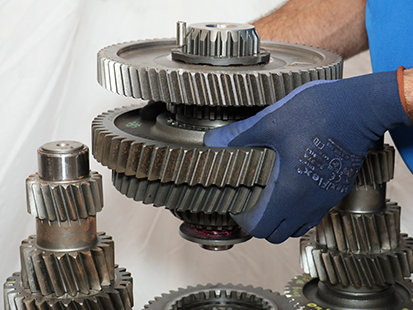
Remove Wave Spring - Rear.
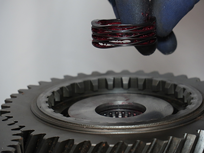
Remove Thrust Washer - Rear.
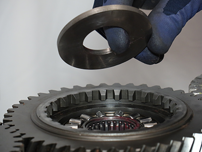
Remove Thrust Bearing - Rear.

Remove Needle Bearing - Rear.
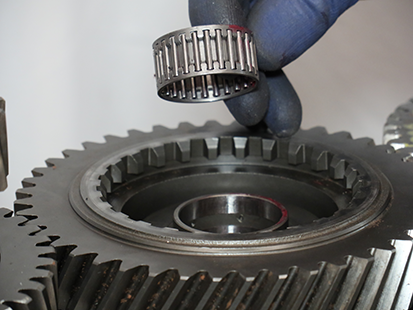
Remove Bearing Race - Rear.
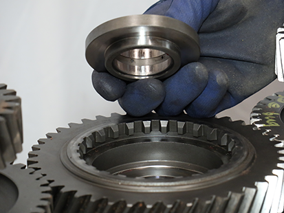
Remove Primary Drive Gear.
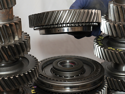
Remove Lower Countershaft.
Caution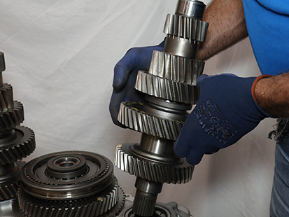
Remove Upper Countershaft.
Caution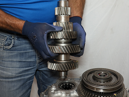
Remove Spherical Washer- Front.
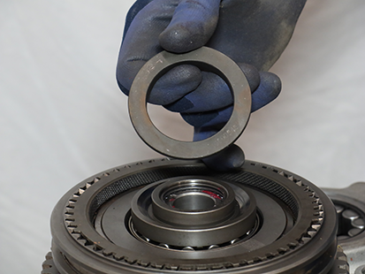
Remove Bearing Race - Front.

Remove Needle Bearing - Front.
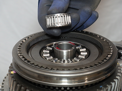
Remove Thrust Bearing - Front.
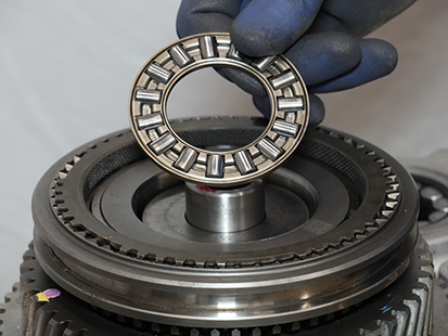
Remove Synchronizer Ring.
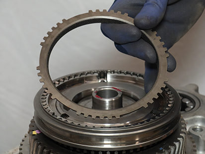
Slowly lift Synchronizer Sliding Sleeve up until Synchronizer Rollers are free from synchronizer assembly.
Notice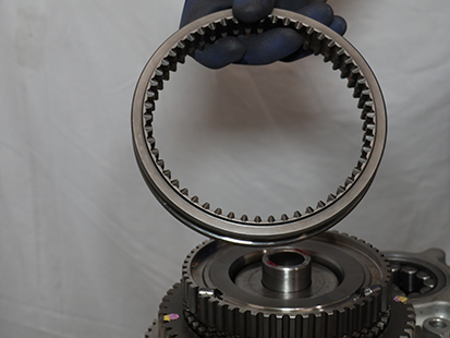
Remove 3 Synchronizer Rollers.
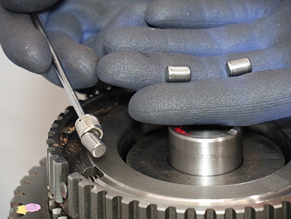
Remove 3 Synchronizer Plungers and Springs from Synchronizer hub.

Remove Thrust Washer - Front.

Remove Wave Spring - Front.

Disassemble the Main Shaft and Replace Main Shaft Selective Washer
Note: This procedure is only required if Main Shaft End-Play is out of range and a thicker Selective Washer is required.
Place Main Shaft Assembly horizontally on a clean flat surface.
CautionRemove Rail C Sliding Clutch.
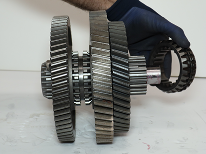
Place Main Shaft assembly vertically on a clean flat surface.
Caution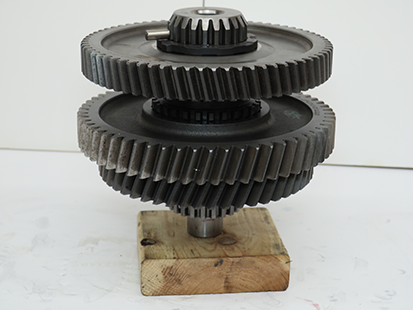
Remove Main Shaft Key while inserting 5/32 OD air line.
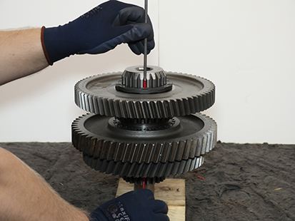
Rotate and remove the Main Shaft Selective Washer above Reverse Gear.
Note: The Main Shaft Selective Washer above Reverse Gear is available in 3 thicknesses; 6.525, 6.712 or 6.900 mm to control Main Shaft End-Play.
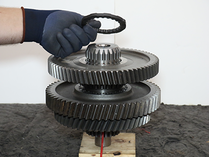
Assemble and Install the Main Shaft with Replaced Main Shaft Selective Washer
Install and rotate the Ideal Main Shaft Selective Washer above Reverse Gear recorded in Step 6 of the Main Shaft End-Play Service Procedure.
Note: The Main Shaft Selective Washer is available in 3 thicknesses: 6.525, 6.712 or 6.900 mm.

Slide the 5/32 OD air line up to align and hold washer in place.
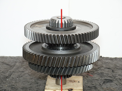
Install Main Shaft Key at the same spline as the 5/32 OD air line.
Note: Insert Main Shaft Key while removing air line.

Install a magnet on Main Shaft Key to hold the key in place during final Main Shaft Assembly and installation into transmission.
Note: Remove magnet from Main Shaft Key after installation of Main Shaft Assembly onto transmission.
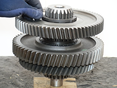
Place Main Shaft Assembly horizontally on a clean flat surface.
CautionInstall Rail C Sliding Clutch and align the double slot with Main Shaft Key.
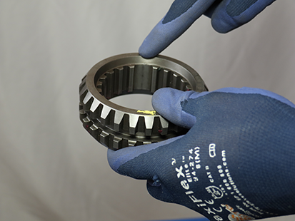
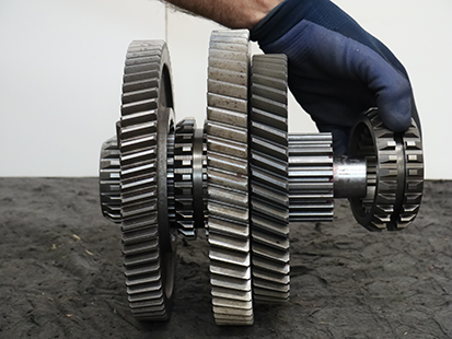
Apply transmission assembly lube to Wave Spring - Rear and install to Main Shaft.
NoticeNote: Transmission assembly lube holds Wave Spring - Rear in place during Main Shaft Assembly installation.


Apply transmission assembly lube to Thrust Washer - Rear and install to Main Shaft.
Note: Transmission assembly lube holds Thrust Washer - Rear in place during Main Shaft Assembly installation.


Install a magnet onto the Main Shaft Key.
Note: The magnet holds the key in position during Main Shaft Assembly installation.

Slide and hold Rail C Sliding Clutch into Secondary Driven Gear.

Install Main Shaft Assembly onto Primary Drive Gear and align gearing.
Caution
Remove magnet from Main Shaft Key.
Notice
If removed, install Upper Lube Tube into Clutch Housing and install 8 mm cap screw and torque to 8–10 Nm (6–13 lb–ft).


If removed, install Lower Lube Tube into Clutch Housing and 8 mm cap screw, torque to 8–10 Nm (6–13 lb–ft).


Perform steps to Install the Main Housing without Gasket Sealant and remeasure Main Shaft End-Play.
Caution
Install Main Housing
Clean the sealing surfaces on the transmission Main Housing and Rear Housing with gasket remover and a plastic scraper. Let air dry then wipe with a clean dry cloth.
NoticeInspect threaded bolt holes for debris and clean if necessary.
NoticeSlide O-ring over the Clutch Housing Inertia Brake air passage alignment pin until fully seated in groove.


Apply gasket sealant with a bead width of 1.4-2.4 mm (0.055-0.094 inch) to clutch housing as shown in pattern below.
NoticeNote: Parts must be assembled within 10 minutes of applying gasket sealant.
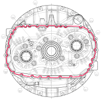
Install Lower Countershaft Pilot Tool (RR1071TR) onto Lower Countershaft above rear bearing race.

Install Upper Countershaft Pilot Tool (RR1072TR) onto the Upper Countershaft above rear bearing race.

Install and hand tighten 2 Rear Housing 90-degree Lifting Eyes and 15 mm cap screws to Main Housing.
NoticeNote: Install 90-degree Lifting Eyes 180-degrees apart to ensure even lifting.

Install and hand tighten 2 Rear Housing Alignment Pins (RR1090TR) into the Clutch Housing as shown below.

Lift, align and install Main Housing to Clutch Housing.
CautionNoticeNote: Using a flat tipped screwdriver, rotate the Reverse Idler Gears to align the gearing and allow Main Housing to fully seat onto the Clutch Housing.

Remove 2 Rear Housing Alignment Pins (RR1090TR).

Remove 2 Rear Housing 90-degree Lifting Eyes and 15 mm cap screws from Main Housing.
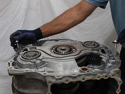
Re-install 2 Rear Housing 90-degree Lifting Eyes to the Rear Housing and torque to 49.6-55.5 Nm (36-40 lb-ft).
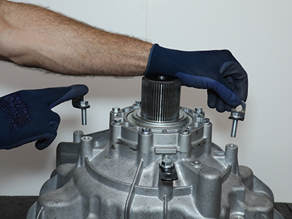
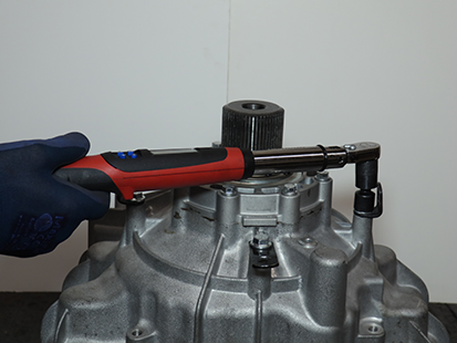
Install 19 external and 6 internal Main Housing 16 mm cap screws and torque to 44–51 Nm (33–38 lb–ft) in a criss-cross pattern.
Notice

Install the Oil Pump Assembly
Install O-ring to the Oil Pump/Range Spacer.
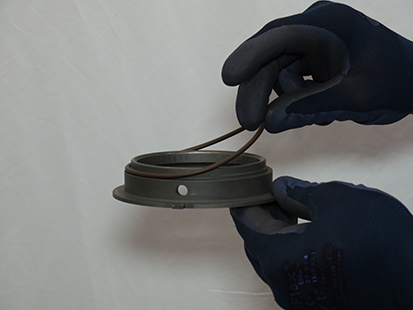
Install Oil Pump/Range Spacer with O-ring and align tab with groove in Oil Pump Assembly.
Notice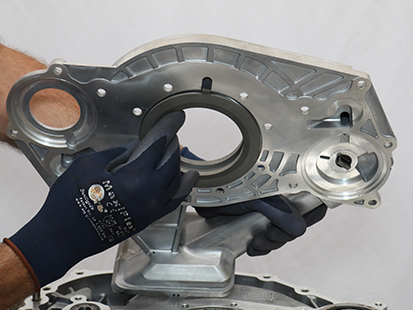
While holding the Oil Pump/Range Spacer in place, align oil pump drive key with slot on Lower Countershaft and install Oil Pump Assembly to Main Housing.
CautionNotice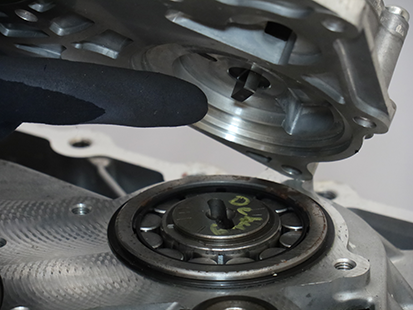
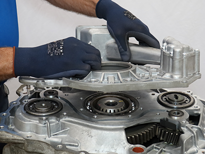
Press Oil Pump Assembly to ensure it sits flat on Main Housing sealing surface.
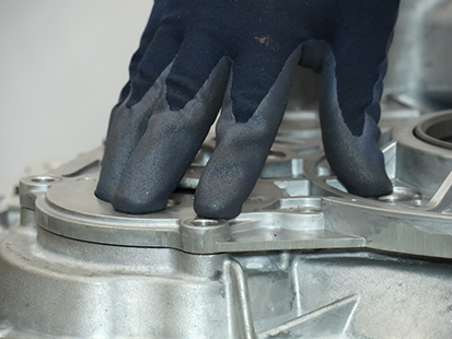
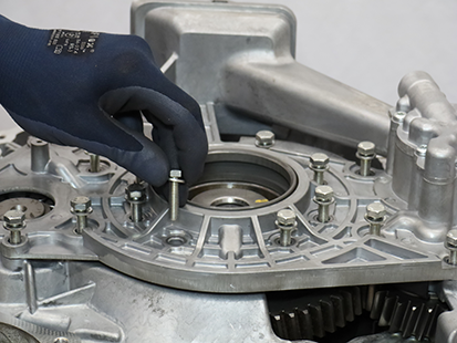
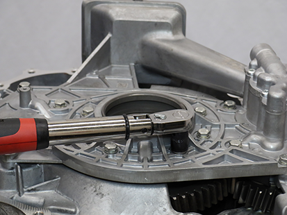
Install 18 Oil Pump Assembly 13 mm cap screws and torque to 21–23 Nm (16–18 lb–ft) in a criss-cross pattern.
Install the Rear Housing
Clean the sealing surfaces on the transmission Main Housing and Rear Housing with gasket remover and a plastic scraper. Let air dry then wipe with a clean dry cloth.
NoticeInspect threaded bolt holes for debris and clean if necessary.
Apply Gasket Sealant with a bead width of 1.4-2.4 mm (0.055-0.094 inch) to the transmission Main Housing sealing surface following the pattern below.
NoticeNote: Parts must be assembled within 10 minutes of applying Gasket Sealant.

Install and hand tighten 2 Rear Housing Alignment Pins (RR1090TR) 180-degrees apart.
Caution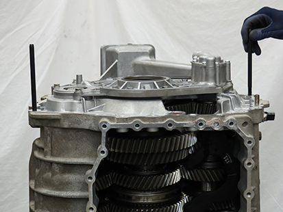
Lift and install the Rear Housing Assembly on to the Main Housing.
WarningNoticeNote: Align the Rear Housing to the alignment pins and align Shift Rail E into the Main Housing during installation.
Note: Rotate Output Shaft to align gearing and allow Rear Housing Assembly to fully seat on Main Housing.
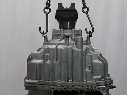
Install the 3 Rear Housing Threaded 16 mm cap screws at the 3 paint mark locations.
Note: Two cap screws are used to mount the harness bracket and the third is used by the OEM for additional attachment points.
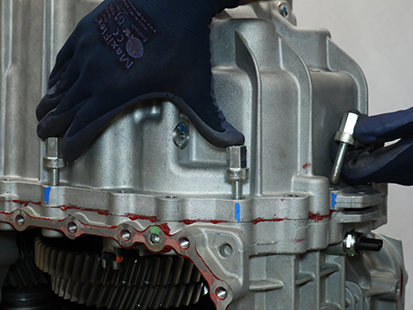
Remove the 2 Rear Housing Alignment Pins (RR1090TR).
Install the remaining 21 Rear Housing 16 mm cap screws and torque to 44.5 - 51.5 Nm (33-38 lb-ft) in a criss-cross pattern.
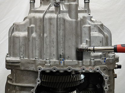
Lift transmission horizontally onto a bench.
WarningNotice
Secure Transmission (Horizontal)
Securely place transmission in the horizontal position with the front side down.
WarningNotice
Install the Input Shaft Snap Ring
Remove Front Bearing Capture Plate (RR1085TR-7) from Clutch Housing.
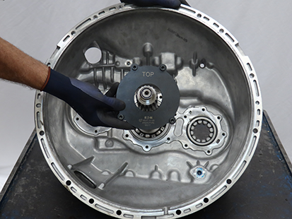
Install Input Shaft Snap Ring.
NoticeNote: The snap ring will not install if Input Shaft is not fully seated into Input Shaft Bearing.
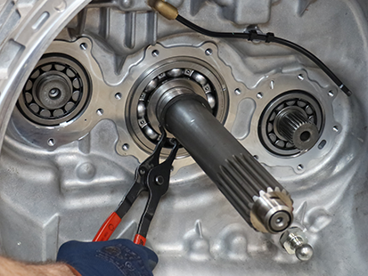
Install the Input Shaft Cover
Clean sealing surfaces on the clutch housing and Input Shaft Cover.
Slide the Input Shaft Cover over the Input Shaft.
Note: Align “TOP” at 12 o’clock.
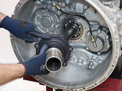
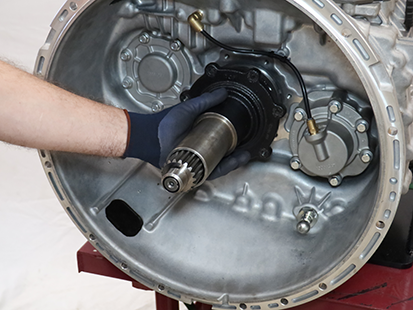
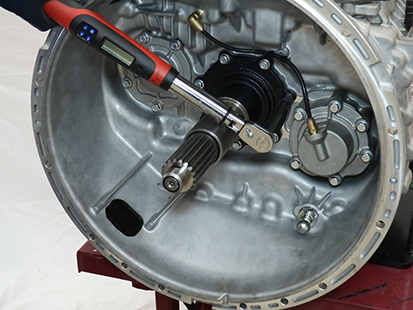
Install the 7 Input Shaft Cover 13 mm cap screws and torque to 21-25 Nm (16-19 lb-ft) in a criss-cross pattern.
Install Lower Countershaft Snap Ring and Flat Washer
Install Lower Countershaft Flat Washer and Snap Ring.
Notice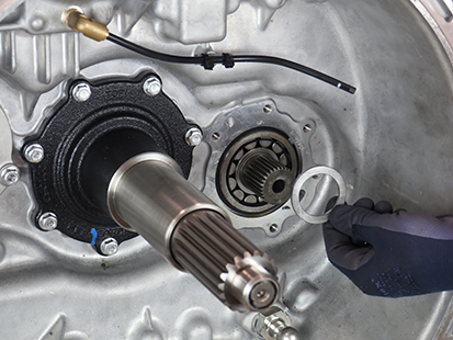
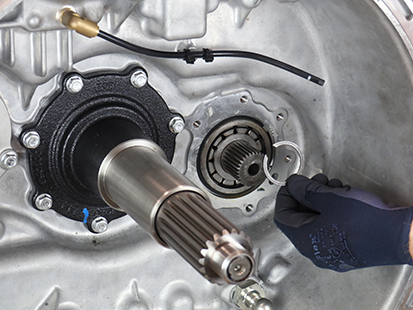
Install the Lower Countershaft Cover and Inertia Brake
Clean sealing surfaces on the Clutch Housing and Inertia Brake Housing.Install the Inertia Brake Cover and Housing as an assembly over the Lower Countershaft, rotate the assembly to align the Friction Discs to the Lower Countershaft splines and seat the assembly to the clutch housing.
Note: Reference RRMT0027 - Clutch Housing Front Cover Kit for new Inertia Brake Housing part number, additional O-ring part number, and installation instructions.

While holding the Inertia Brake Housing to the clutch housing, remove the Inertia Brake Cover.
Notice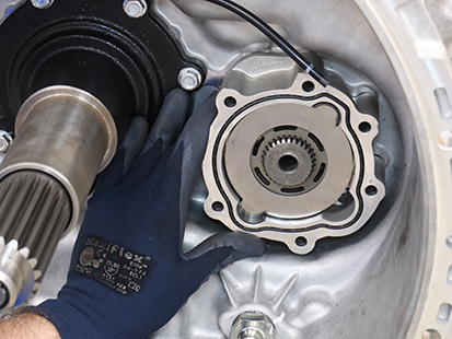
Install the Return Spring into the Lower Countershaft.
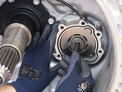
Install the Piston Pin into the Lower Countershaft.
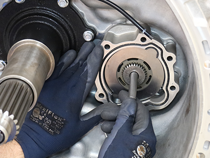
Install the Inertia Brake Cover onto the housing.
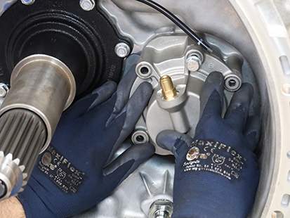
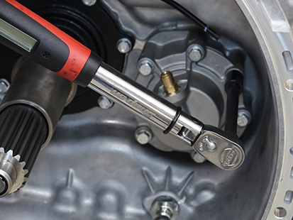
Install the 6 13 mm cap screws and torque to 21-25 Nm (16-19 lb-ft) in a criss-cross pattern.
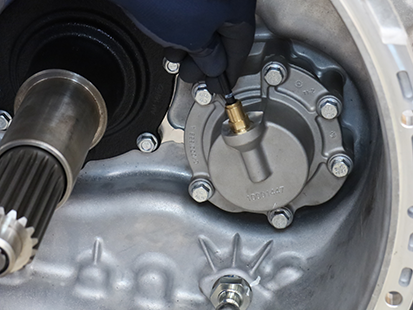
Insert air line in push-to-connect fitting on the Inertia Brake Cover.
Install Upper Countershaft Snap Ring and Flat Washer
Install Upper Countershaft Flat Washer and Snap Ring.
Notice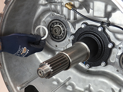
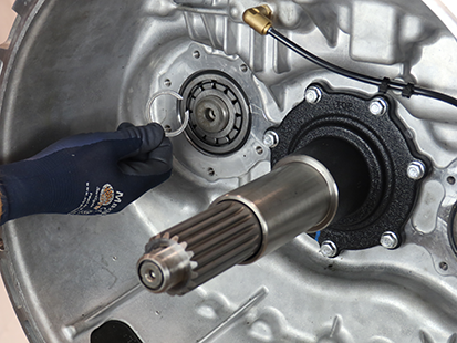
Install the Upper Countershaft Cover
Clean the sealing surfaces on the clutch housing and the Upper Countershaft Cover.
Note: A new Upper Countershaft Cover Seal is required when reinstalling or an oil leak may occur. Reference RRMT0027 - Clutch Housing Front Cover Kit for new Upper Countershaft Cover part number, additional O-ring part number, and installation instructions.
Insert the Upper Countershaft Cover Seal into the groove until fully seated.
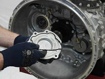
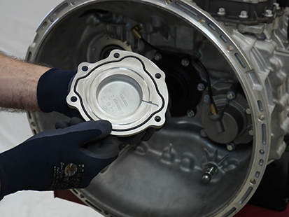
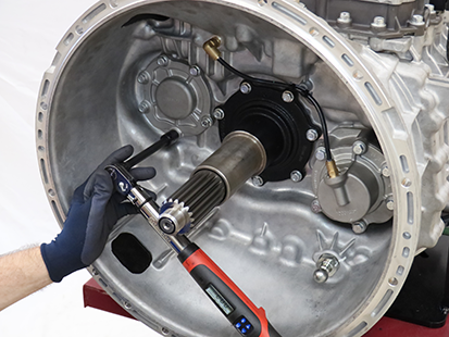
Install the Upper Countershaft Cover to the Clutch Housing.
Install the six 13 mm cap screws and torque to 21-25 Nm (16-19 lb-ft) in a criss-cross pattern.
Install the Harness Bracket
Note: This procedure contains installing the Harness Bracket without the Mechatronic Transmission Module (MTM).
Install Harness Bracket.
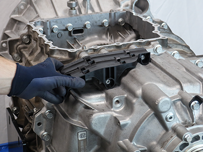
Install 3 Harness Bracket 10 mm cap screws and torque to 8.8 - 10.4 Nm (6-8 lb-ft).

Install the Output Speed Sensor
Clean the sensor bore.
NoticeApply a light coat of transmission oil to the sensor O-ring.
Install the Output Speed Sensor into the bore.
Note: The Sensor may need to be twisted and pushed into the bore.

Install the Output Speed Sensor 10 mm cap screw and torque to 8.8-10.4 Nm (6-8 lb-ft).
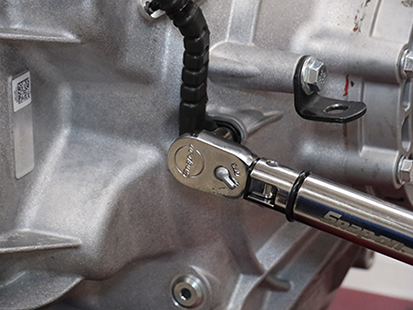
Press the 2 harness press-in retainers into the Main Housing and the bracket on the rear housing.
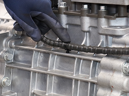
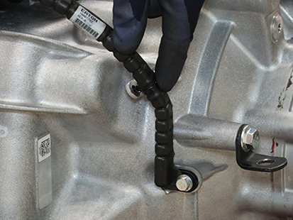
Secure the Output Speed Sensor Harness to the Harness Bracket with a tie strap.
Caution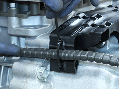
Install the Mechatronic Transmission Module (MTM)
Note: If replacing original equipment MTM with new/replacement MTM locate new/replacement MTM part information tag and record Part Number and Serial Number. Refer to Component Identification section. Part Number and Serial Number are required to properly configure TCM after MTM installation.
Place the transmission in a horizontal position.
NoticeClean the sealing surfaces on the transmission and Mechatronic Transmission Module (MTM) with gasket remover and a plastic scraper. Let air dry then wipe with a clean dry cloth.
NoticeInspect threaded bolt holes for debris and clean if necessary.
NoticeInstall the Rail B Engagement Tool (RR1088TR) to the Main Housing and hand tighten with 2 MTM cap screws.
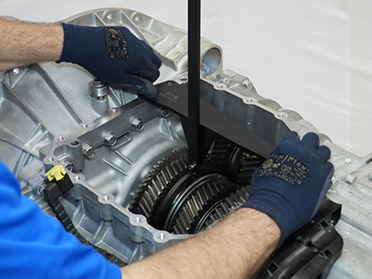
Shift the Rail B Synchronizer to neutral.
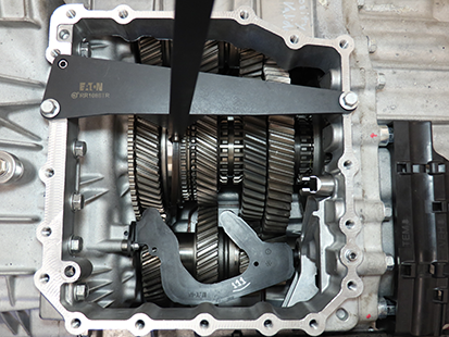
Remove the Rail B Engagement Tool.
Move Rail C and Rail D sliding clutches to neutral.
Notice
Install the Confirm-Neutral Gauge (RR1086TR-2) into the slots of the synchronizer and sliding clutches.
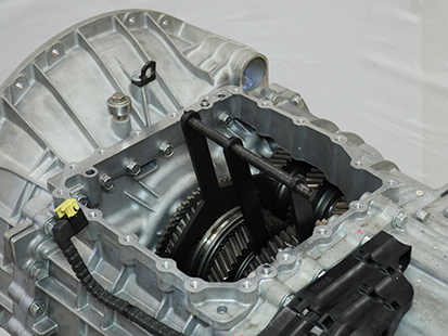

Install the MTM Alignment Tool (RR1086TR-1) onto the main housing.
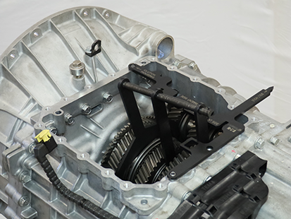
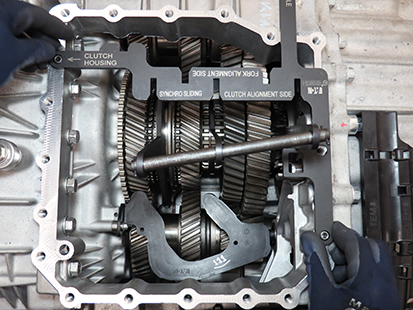
Verify synchronizer and sliding clutches are in neutral by sliding Confirm-Neutral Gauge into the slots of MTM Alignment Tool.
Note: If the gauge does not slide into the alignment tool slots, neutral is not achieved. Go to Step 4.
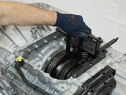
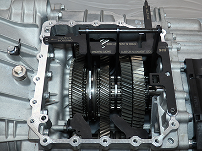
Using the Rail E Lever, move Rail E to neutral.
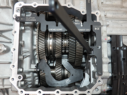
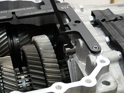
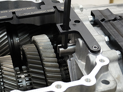
Verify Rail E is in neutral using the Gear Side Actuator end of the Confirm-Neutral Gauge (RR1088TR-2) at Shift Rail E. Rail E is in neutral when end of gauge rests against housing with rail against notch-end of gauge.

Move Shift Rail B in the MTM to neutral. Rail B is in neutral when the ball detent is in the notch of the Rail B yoke assembly.
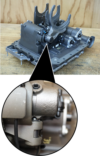
Move Shift Rails C and D in the MTM to neutral. Rails C and D are in neutral when the shift inter-lock is aligned with the notches of the rail yoke assemblies.
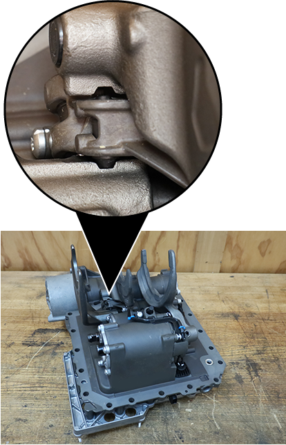
Verify MTM is in neutral. Install the MTM Alignment Tool (RR1086TR-1) into the bolt hole and onto Rail B, C, and D Shift Yokes.
Note: If the MTM Alignment Tool slots do not align with the 3 shift yokes, neutral has not been achieved. Go to Step 13.
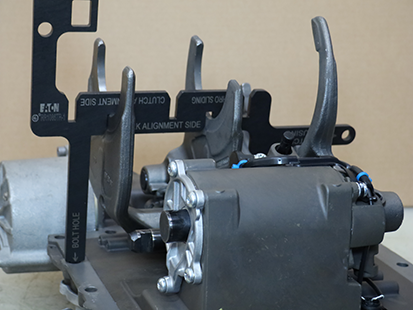
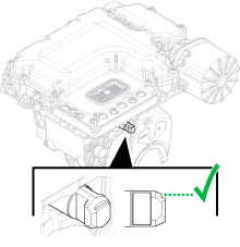
Verify notch on Rail E is facing up.
Note: If MTM is installed on transmission with notch on Rail E facing down, Fault Code/SPN 320/5942 sets Active and transmission does not shift out of neutral.
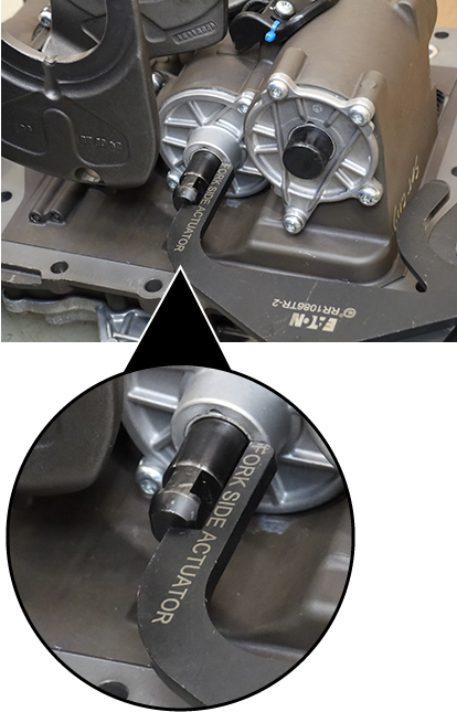
Verify Rail E is in neutral using the Fork Side Actuator end of the Confirm-Neutral Gauge (RR1088TR-2) at Shift Rail E. Rail E is in neutral when end of gauge rests against cover with rail against notch-end of gauge.
Note: If Rail E is not in neutral, slide rail in or out until neutral is achieved.
Slide O-ring over the MTM front alignment pin on the main housing until fully seated in the groove.
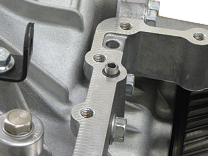
Clean the sealing surfaces on the transmission and Mechatronic Transmission Module (MTM) with gasket remover and a plastic scraper. Let air dry then wipe with a clean dry cloth.
NoticeApply gasket sealant with a bead width of 1.4-2.4mm (0.055-0.094 inch) to the transmission housing sealing surface following the pattern below.
NoticeNote: Parts must be assembled within 10 minutes of applying Gasket Sealant.
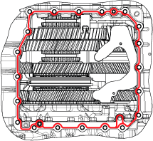
Install MTM onto the transmission housing. Align Rail E in the MTM with the Rail E Shift Rail in the Main Housing.
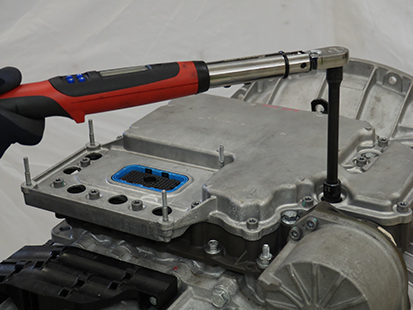
CautionNoticeInstall 20 MTM cap screws and torque to 44.5-51.5 Nm (33-38 lb-ft) in a criss-cross pattern.
Note: 13 mm (x18), 15 mm (x2) cap screws.
Install the Transmission Control Module (TCM)
Note: TCM can be installed with transmission in-vehicle.
Install the TCM Seal on the 74-Way Harness Connector.
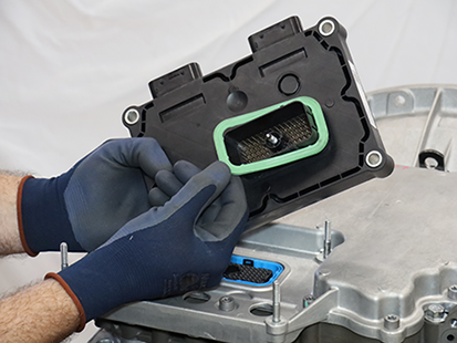
Align the TCM to the 74-Way Harness Connector and TCM studs, then install the TCM.
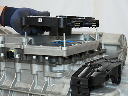
Torque the TCM 7 mm Jackscrew to 3.0-4.0 Nm (26.6-35.4 lb-in).
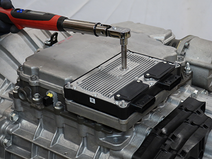
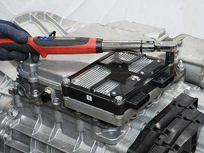
Install the TCM Cover over the 4 TCM studs and torque the 4 TCM Cover Nuts to 8.8-10.4 Nm (78-92 lb-in) in a criss-cross pattern.
Note: TCM Cover nuts are 10 or 13 mm.
Remove the Linear Clutch Actuator (LCA)
Loosen the 4 LCA cap screws 1-2 turns each with a T45 Torx.
NoticeNote: Residual air pressure in the LCA cylinder exhausts between the LCA and MTM housing when the cap screws are loosened.
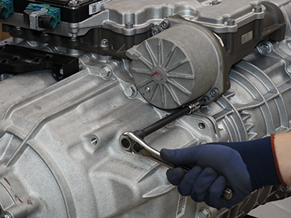
Remove the 4 LCA cap screws
Remove the LCA from the MTM.
Note: LCA piston rod end is seated in the release yoke socket; pull to release rod end from socket.
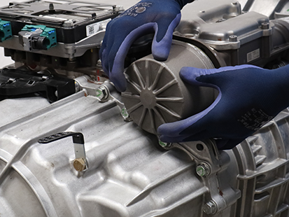
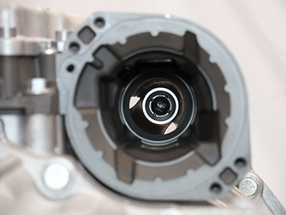
Inspect the plastic socket insert in the release yoke through the LCA opening using a flashlight to verify none of the fingers are missing or damaged.
Note: If the plastic insert is damaged, replace the release yoke assembly.
Reset and Install Linear Clutch Actuator (LCA)
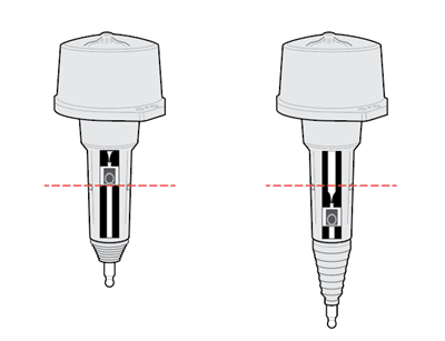
Inspect LCA to determine next steps, reference images below:
- If LCA is locked in the reset position, go to Install Linear Clutch Actuator (LCA).
- If LCA is not locked in the reset position, go to Step 2.
Locked in Reset Position
Not Locked in Reset Position
Place LCA push rod on a clean, flat surface. Tightly grasp LCA housing with both hands and push down on push rod to lock LCA into the reset position.
Caution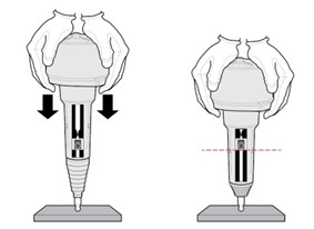
Inspect LCA to determine next steps, reference images below:
- If LCA remains locked in the reset position, go to Step 4.
- If LCA does not remain locked in the reset position, go to Step 2, repeat reset procedure.
Note: If LCA cannot be locked into the reset position, replace LCA.
CautionLocked in Reset Position
Not Locked in Reset Position
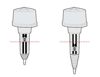
Clean all sealing surfaces on the MTM and LCA with a lint free cloth.
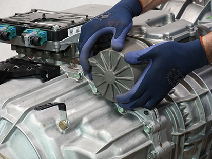
NoticeInsert the LCA into the MTM.
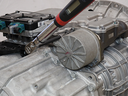
Install 4 LCA T45 cap screws and torque to 23-28 Nm (17-21 lb-ft) in a criss-cross pattern.
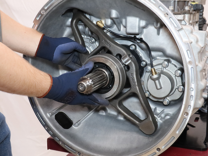
Install the Release Bearing and Clutch Release Yoke
Install the upper Release Yoke socket over the rod end of the Linear Clutch Actuator (LCA) and press until attached.
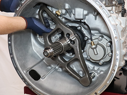
Install the lower Release Yoke socket over the lower pivot on the clutch housing and press until attached.
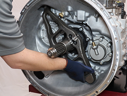
Slide the Release Bearing over the input shaft and into the Release Yoke.
Install the Transmission
Refer to OEM guidelines for transmission installation.
Connect negative battery cable.
Fill Oil
Note: Perform the transmission fill procedure with transmission installed in vehicle to ensure proper transmission angle.
Remove the Oil Fill Plug with a 6 mm hex key.
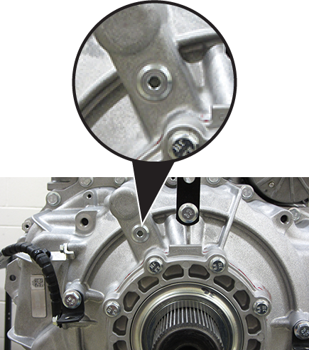
Place a suitable container under the Oil Check Plug and remove the Oil Check Plug with a 6 mm hex key.
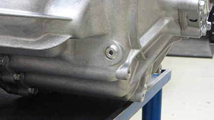
Fill the transmission with PS-386 lube until a small amount of oil runs out of the Oil Check Plug hole.
Note: Fill capacity is approximately 7.5-8.5 liters (16-18 pints) depending on the transmission angle.
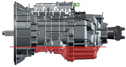
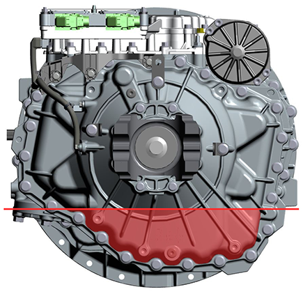
Inspect Oil Check Plug and O-ring for damage. If damaged, replace the Oil Check Plug; O-ring is serviced with plug.
Install the Oil Check Plug (6 mm) and torque to 24.5-29.5 Nm (18-22 lb-ft).
Notice
Inspect Oil Fill Plug and O-ring for damage. If damaged, replace the Oil Fill Plug; O-ring is serviced with plug.
Install the Oil Fill Plug (6 mm) and torque to 24.5-29.5 Nm (18-22 lb-ft).
Notice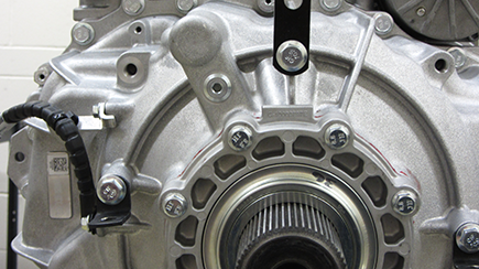
Clutch and Rail Calibration
To ensure proper operation, the TCM, clutch, MTM and transmission require a Clutch and Rail Calibration. Calibrations are automatically initiated when:
- LCA is in the reset position
- Transmission in “N” (Neutral)
- Key on engine running
- Vehicle air system pressure at operating range
Note: Vehicle display may indicate a flashing “CC” and “F” in gear display.
Set vehicle parking brake and chock wheels.
Ensure the driveline is connected between the transmission and axle.
Note: Clutch and Rail Calibrations cannot complete if the transmission output shaft is allowed to rotate.
Key on with engine running.
Allow vehicle air pressure to build to governor cut-off.
Note: Clutch and Rail Calibrations automatically initiate when vehicle air pressure reaches approximately 100 psi.
Ensure “N” (Neutral) is selected and engine is running. Wait approximately 2 minutes for calibrations to complete.
Notice- If vehicle display indicates a solid “N: (Neutral) in gear display, calibrations are complete. Key off, go to Step 6.
- If vehicle display continues to indicate a flashing “CC” and/or “F” in gear display or service transmission message, go to Step 5.
Key off and wait 1 minute.
Key on with engine off.
Connect ServiceRanger.
Go to “Fault Codes”.
- If an Active transmission fault code is set, go to Endurant HD Troubleshooting Guide TRTS0950 Diagnostic Procedure.
- If no Active transmission fault codes are set, select “Clear Eaton Faults” and follow on-screen prompts. Go to Step 9.
Disconnect ServiceRanger.
Key off.
Inspect transmission for a PTO.
- If not PTO-equipped, process complete.
- If PTO-equipped, start the engine and run for 1 to 2 minutes to fill the PTO with oil, key off and repeat the Fill Oil Procedure.
Caution