Fault Code 51: Rail Position Sensor
J1587: MID 130 PID 60 FMI 2, 3, 4, 10 , 11
J1939: SA 3 SPN 60 FMI 2, 3, 4, 10 , 11
Overview
The UltraShift PLUS X-Y Shifter is equipped with a Rail Position Sensor. The X-Y Rail Position Sensor reports lateral movement of the Shift Finger to the Transmission Electronic Control Unit (TECU) as a voltage signal. The X-Y Rail Position Sensor is connected to the TECU via the Transmission Harness.
The TECU performs continuous diagnostics on the circuit to detect a shorted circuit, open circuit or incorrect position reading. Fault Code 51 is set when the TECU has detected either an electrical failure of the X-Y Rail Position Sensor circuit or a mechanical failure within the X-Y Shifter.
Detection
The TECU monitors both the 5-volt X-Y Rail Position Sensor supply and the return voltage signal from the X-Y Rail Position Sensor. If the system detects that either the supply voltage or return voltage is out of range, the fault code is set Active.
Conditions to Set Fault Code Active
FMI 2 – Data Erratic: TECU detects the X-Y Rail Position Sensor return voltage signal is outside of the 0.5–4.5-volt range for 1 second or longer.
FMI 3 – Voltage Above Normal or Shorted High: TECU detects the X-Y Rail Position Sensor supply voltage has exceeded 5.25 volts for 1 second or longer.
FMI 4 – Voltage Below Normal or Shorted Low: TECU detects the X-Y Rail Position Sensor supply voltage is below 4.75 volts for 1 second or longer.
FMI 10 – Abnormal Rate of Change: The reported X-Y Rail Position Sensor return voltage signal changed by more than ±0.2 volts, or finger position moved by more than ±0.093 inches, while the transmission is engaged in gear.
FMI 11 – Root Cause Unknown: The X-Y Rail Position Sensor voltage is out of range.
Fallback
All FMIs
- “F” flashes in gear display.
- Service light flashes (if equipped).
- Transmission remains in current gear.
- Until the fault becomes Inactive, driver may have to shut off engine with transmission in gear.
Conditions to Set Fault Code Inactive
FMI 2: X-Y Rail Position Sensor return voltage signal stays within the 0.5–4.5-volt range for 1 second.
FMI 3, 4: Supply voltage stays within the 4.75–5.25 volt range for 1 second.
FMI 10: X-Y Rail Position Sensor return voltage signal remains consistent (within ±0.2 volts) while the transmission is in gear.
FMI 11: X-Y Rail Position Sensor voltage in range.
Possible Causes
FMI 2, 4, 10, 11
- Transmission Harness
- Bent, spread, corroded or loose terminals
- Wiring shorted to ground, shorted to power or open
- X-Y Shifter
- Bent, spread, corroded or loose terminals
- Wiring shorted to ground, shorted to power or open
- Rail Position Sensor damaged
- TECU
- Internal failure
FMI 3
- TECU
- Internal failure
- Transmission Harness
- Bent, spread, corroded or loose terminals
- Wiring shorted to power
Component Identification
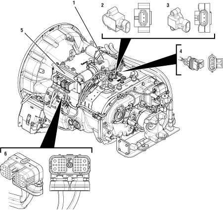 |
1. X-Y Shifter 2. 3-Way Rail Position Sensor (A) 3. 3-Way Rail Position Sensor (B) 4. 3-Way Rail Position Sensor Connector 5. 38-Way Transmission Harness Connector 6. Transmission Electronic Control Unit (TECU) |
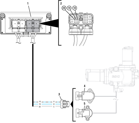 |
1. Transmission Electronic Control Unit (TECU) 2. 38-Way Transmission Harness Connector 3. 3-Way Rail Position Sensor Connector 4. 3-Way Rail Position Sensor (A) 5. 3-Way Rail Position Sensor (B) |
 |
Fault Code 51 Troubleshooting
Record the transmission fault codes, FMIs, occurrences, and timestamps from the Service Activity Report created during the Diagnostic Procedure.
If Fault Code 51 FMI 3, 4, 10, 11 is Active, Go to Step C
If Fault Code 51 FMI 3, 4, 10, 11 is Inactive, Go to Step B
If Fault Code 51 FMI 2 is Active or Inactive, Go to Step D
Set parking brake and chock wheels.
Place transmission in PD Mode. See more about Product Diagnostic (PD) Mode.
Note: Transmission does not enter PD Mode when Active fault codes exist.

Wiggle wiring and connections of the Transmission Harness between the Rail Position Sensor and the TECU.
Exit PD Mode by powering down.
Notice
If any fault codes set Active while wiggling the Transmission Harness, replace Transmission Harness. Go to Step V
If no fault codes set Active while wiggling the Transmission Harness, Go to Step C
Key off.
Disconnect 38-Way Transmission Harness Connector from the TECU.
Inspect 38-Way Connector body for damage and bent, spread, corroded or loose terminals.
Measure resistance between 38-Way Transmission Harness Connector Pin 18 and ground. Record reading(s) in table.
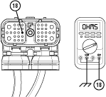
Compare reading(s) in table.
If connector is damaged, replace Transmission Harness. Go to Step V
If readings are in range, Go to Step E
If readings are out of range, replace Transmission Harness. Go to Step V
| Pins | Range | Reading(s) |
|---|---|---|
| 18 to Ground | Open Circuit (OL) |
Key off.
Disconnect 38-Way Transmission Harness Connector from the TECU.
Verify the connector is free from contamination and corrosion; the terminals are not bent, spread or loose; and there is no damage to the connector body.
Inspect the TECU side of the 38-Way Transmission Harness Connector for contamination and corrosion; the terminals are not bent, spread or loose; and there is no damage to the connector body.
If no contamination or damage is found, Go to Step E
If contamination or damage is found, replace the Transmission Harness. Go to Step V
Inspect 3-Way Rail Position Sensor, reference image below.

If equipped with a 3-Way Rail Position Sensor (A), Go to Step F
If equipped with a 3-Way Rail Position Sensor (B), Go to Step J
Key off.
Measure resistance between 38-Way Transmission Harness Connector Pin 18 and Pin 19. Record reading(s) in table.
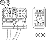
Measure resistance between 38-Way Transmission Harness Connector Pin 18 and Pin 20. Record reading(s) in table.
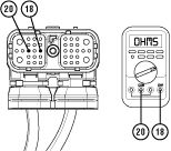
Compare reading(s) in table.
If all readings are in range, Go to Step G
If either reading is out of range, Go to Step H
| Pins | Range | Reading(s) |
|---|---|---|
| 18 to 19 | 150 – 200 ohms | |
| 18 to 20 | 5.5k – 6.5k ohms |
Determine which FMI set for Fault Code 51.
If FMI 2, 10 or 11 set, replace Transmission Harness. Go to Step V
If FMI 3 or 4 set, replace Transmission Electronic Control Unit (TECU) and Transmission Harness. Go to Step V
Key off.
Disconnect 3-Way Transmission Harness Connector from 3-Way Rail Position Sensor (A).
Inspect 3-Way Connector body for damage and bent, spread, corroded or loose terminals.
Measure resistance between 3-Way Rail Position Sensor (A) Body Pin A and Pin B. Record reading(s) in table.
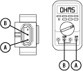
Measure resistance between 3-Way Rail Position Sensor (A) Body Pin A and Pin C. Record reading(s) in table.
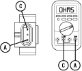
Compare reading(s) in table.
If the connector is damaged, replace Transmission Harness. Go to Step V
If all readings are in range, Go to Step I
If either reading is out of range, replace X-Y Shifter. Go to Step V
| Pins | Range | Reading(s) |
|---|---|---|
| A to B | 150 – 200 ohms | |
| A to C | 5.5k – 6.5k ohms |
Determine which FMI set for Fault Code 51.
If FMI 2,10 or 11 set, replace Transmission Harness. Go to Step V
If FMI 3 or 4 set, replace Transmission Electronic Control Unit (TECU) and Transmission Harness. Go to Step V
Key off.
Measure resistance between 38-Way Transmission Harness Connector Pin 18 and Pin 19. Record reading(s) in table.

Measure resistance between 38-Way Transmission Harness Connector Pin 18 and Pin 20. Record reading(s) in table.

Compare reading(s) in table.
If all readings are in range, Go to Step K
If either reading is out of range, Go to Step L
| Pins | Range | Reading(s) |
|---|---|---|
| 18 to 19 | 150 – 200 ohms | |
| 18 to 20 | 180 – 230 ohms |
Determine which FMI set for Fault Code 51.
If FMI 2, 10 or 11 set, replace Transmission Harness. Go to Step V
If FMI 3 or 4 set, replace Transmission Electronic Control Unit (TECU) and Transmission Harness. Go to Step V
Key off.
Disconnect 3-Way Transmission Harness Connector from 3-Way Rail Position Sensor (B).
Inspect 3-Way Connector body for damage and bent, spread, corroded or loose terminals.
Measure resistance between 3-Way Rail Position Sensor (B) Body Pin A and Pin B. Record reading(s) in table.
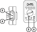
Measure resistance between 3-Way Rail Position Sensor (B) Body Pin A and Pin C. Record reading(s) in table.
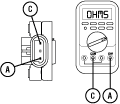
Compare reading(s) in table.
If the connector is damaged, replace Transmission Harness. Go to Step V
If all readings are in range, Go to Step M
If either reading is out of range, replace X-Y Shifter. Go to Step V
| Pins | Range | Reading(s) |
|---|---|---|
| A to B | 150 – 200 ohms | |
| A to C | 180 – 230 ohms |
Determine which FMI set for Fault Code 51.
If FMI 2,10 or 11 set, replace Transmission Harness. Go to Step V
If FMI 3 or 4 set, replace Transmission Electronic Control Unit (TECU) and Transmission Harness. Go to Step V
Key off.
Reconnect all connectors and verify that all components are properly installed.
Key on with engine off.
Clear fault codes using ServiceRanger.
Drive vehicle and attempt to reset the code or duplicate the previous complaint.
Check for fault codes using ServiceRanger.
If no fault codes set Active and the vehicle operates properly, test complete.
If Fault Code 51 sets Active during the test drive, Go to Step A
If a fault code other than 51 sets Active, troubleshoot per Fault Code Isolation Procedure Index.