Fault Code 61: Rail Motor Circuit
J1587: MID 130 SID 39 FMI 1, 5, 6, 12
J1939: SA 3 SPN 772 FMI 1, 5, 6, 12
Overview
The UltraShift PLUS Transmission is equipped with an X-Y Shifter that selects a transmission gear. The X-Y Shifter motors are controlled with electrical current supplied by the TECU to move the Shift Finger either side-to-side (rail selection) or fore-and-aft (gear engagement and disengagement). Fault Code 61 indicates a failure with the circuit controlling the Rail Motor and the side-to-side movement of the X-Y Shift Finger.
Detection
The system can identify an issue with the X-Y Shifter Rail Motor circuit, the TECU rail motor controller or the power and ground connections to the TECU under the following conditions:
- FMI 1, 5 and 12 can be detected when the X-Y Rail Motor is energized.
- FMI 6 can be detected when the X-Y Rail Motor is not energized.
Conditions to Set Fault Code Active
FMI 1 – Data Valid but Below Normal: Transmission fails to complete a shift and the measured current draw of the Rail Motor is below expected values, but no short to ground or open circuit condition is detected.
FMI 5 – Current Below Normal or Open Circuit: Transmission fails to complete a shift, the measured current draw of the Rail Motor is below expected values and an open circuit or short to ground condition is detected for 0.5 seconds.
FMI 6 – Current Above Normal or Shorted Circuit: TECU detects a short to power on the Rail Motor circuit for 0.5 seconds at power up or prior to a shift.
FMI 12 – Bad Intelligent Device: Transmission fails to complete a shift and the TECU detects intermittent fluctuations in supply voltage due to poor connections, shorted Rail Motor circuit or a hardware failure of the TECU.
Fallback
All FMIs
- “F” flashes in gear display.
- Service light flashes (if equipped).
- Engine may not crank.
- Transmission may not engage a gear from neutral.
- Transmission does not shift while vehicle is moving.
- Until fault becomes Inactive, driver may have to shut off engine with transmission in gear.
Conditions to Set Fault Code Inactive
FMI 1, 5, 12: Set Inactive when the shift is completed.
FMI 6: An electrical short or open circuit is not detected for 0.5 seconds.
Possible Causes
FMI 1, 5
- Transmission Harness
- Bent, spread, corroded or loose terminals
- Wiring shorted to ground or open
- X-Y Shifter Rail Motor
- Bent, spread, corroded or loose terminals
- Wiring shorted to ground or open
- Rail Motor shorted to ground, partial short to ground, or open
- Rail Motor internal failure
- TECU
- Internal failure
FMI 6
- Transmission Harness
- Wiring shorted to power
- TECU
- Internal failure
FMI 12
- Vehicle Power Supply
- Poor power or ground supply to TECU (may be in conjunction with Fault Codes 33 or 34)
- Bent, spread, corroded or loose terminals
- Wiring shorted to ground, shorted to power or open
- Vehicle Batteries
- Internal failure
- Vehicle 30-amp Battery Fuse
- Bent, spread, corroded or loose terminals
- Fuse missing or improperly seated
- TECU
- Internal failure
Component Identification
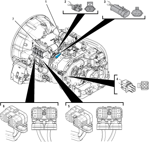 |
1. X-Y Shifter 2. 2-Way Rail Motor Connector (black) 3. 2-Way Rail Motor Connector Body (black) 4. 4-Way Diagnostic Connector 5. 38-Way Transmission Harness Connector 6. 38-Way Vehicle Harness Connector 7. Transmission Electronic Control Unit (TECU) |
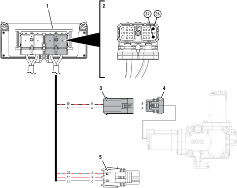 |
1. Transmission Electronic Control Unit (TECU) 2. 38-Way Transmission Harness Connector 3. 2-Way Rail Motor Connector Body (black) 4. 2-Way Rail Motor Connector (black) 5. 4-Way Diagnostic Connector |
 |
Fault Code 61 Troubleshooting
Record the transmission fault codes, FMIs, occurrences, and timestamps from the Service Activity Report created during the Diagnostic Procedure.
If either Fault Codes 33 or 34 are Active, troubleshoot per Fault Code Isolation Procedure Index.
If Fault Code 61 is Active and Fault Codes 33 or 34 are Inactive or not set, Go to Step D
If Fault Code 61 is Inactive and Fault Codes 33 or 34 are Inactive or not set, Go to Step B
Key off.
Set parking brake and chock wheels.
Load test each vehicle battery per OEM specifications. Record reading(s).
If any battery does not pass the Load Test, refer to OEM guidelines for repair or replacement of batteries. Go to Step V
If all batteries pass the Load Test, Go to Step C
| Battery | Voltage Drop | Load Test Status (Pass/Fail) |
|---|---|---|
| 1 | ||
| 2 | ||
| 3 | ||
| 4 | ||
| 5 |
Set parking brake and chock wheels.
Place transmission in PD Mode. See more about Product Diagnostic (PD) Mode.
Note: Transmission does not enter PD Mode when Active fault codes exist.

Wiggle wiring and connections between 38-Way Vehicle Harness Connector at the TECU and vehicle battery supply. Look for signs of rubbing or chafing.
Wiggle wiring and connections between 38-Way Transmission Harness Connector at the TECU and the black (X-Rail Motor) 2-Way Transmission Harness Connector.
Wiggle wiring and connections between 38-Way Connector at the TECU and the blue (Y-Gear Motor) 2-Way Transmission Harness Connector.
Exit PD Mode by powering down.
Notice
If Fault Code 61 or 63 set Active immediately and continuously after entering PD Mode, Go to Step D
If any fault code sets Active while wiggling the Vehicle Harness, refer to OEM guidelines for repair or replacement of the OEM wiring. Go to Step V
If any fault code sets Active while wiggling the Transmission Harness, replace Transmission Harness. Go to Step V
If no fault code sets Active while wiggling either harness, Go to Step D
Determine which FMI set for Fault Code 61.
If FMI 1, 5 or 12 set, Go to Step E
If FMI 6 set, replace Transmission Electronic Control Unit (TECU). Go to Step V
Key off.
Disconnect 38-Way Transmission Harness Connector from the TECU.
Inspect 38-Way Connector body for damage and bent, spread, corroded or loose terminals.
Measure resistance between 38-Way Connector Pin 35 and Pin 37. Record reading(s) in table.
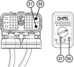
Measure resistance between 38-Way Connector Pin 35 and ground. Record reading(s) in table.
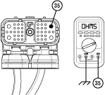
Compare reading(s) in table.
If readings are in range, Go to Step F
If any reading is out of range, Go to Step H
| Pins | Range | Reading(s) |
|---|---|---|
| 35 to 37 | 10 ohms or less | |
| 35 to Ground | Greater than 5K ohms or Open Circuit (OL) |
Determine which FMI set for Fault Code 61.
If FMI 1 or 12 set, Go to Step I
If FMI 5 set, Go to Step G
Reconnect 38-Way Transmission Harness to the TECU.
Disconnect black 2-Way Rail Motor Connector from Transmission Harness.
Remove cover of the 4-Way Diagnostic Connector.
Measure resistance between 2-Way Connector Body Pin A and the 4-Way Connector Pin C. Record reading(s) in table.
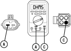
Reverse meter leads and take the same resistance measurement between the 2-Way Connector Body Pin A and the 4-Way Connector Pin C. Record reading(s) in table.
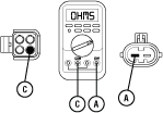
Compare reading(s) in table.
If readings are in range, replace X-Y Shifter. Go to Step V
If any reading is out of range, replace Transmission Electronic Control Unit (TECU). Go to Step V
| Pins | Range | Reading(s) |
|---|---|---|
| A to C | 15k ohms or greater | |
| C to A | 15k ohms or greater |
Key off.
Disconnect black 2-Way Rail Motor Connector from Transmission Harness.
Inspect 38-Way Connector body for damage and bent, spread, corroded or loose terminals.
Measure resistance between the black 2-Way Connector Pin A and Pin B. Record reading(s) in table.
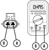
Measure resistance between 2-Way Connector Pin A and ground. Record reading(s) in table.

Compare reading(s) in table.
If readings are in range, replace Transmission Harness. Go to Step V
If any reading is out of range, replace the X-Y Shifter. Go to Step V
| Pins | Range | Reading(s) |
|---|---|---|
| A to B | 10 ohms or less | |
| A to Ground | Greater than 5K ohms or Open Circuit (OL) |
Key off.
Verify TECU battery power and ground supply from the OEM Vehicle Harness is connected properly and not corroded, damaged or loose.
Disconnect 38-Way Vehicle Harness Connector from TECU.
Inspect 38-Way Connector body for damage and bent, spread, corroded or loose terminals.
Load test the Vehicle Power Supply Harness with an external load source. Use a sealed beam headlamp or blower motor attached to Pin 38 (power) and Pin 36 (ground). Load Test for 5 minutes to verify the harness will carry a load with the 30-amp fuse installed.
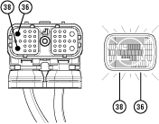
Wiggle the harness during the Load Test from the vehicle batteries to TECU.
If issues are found with the power supply or connectors, refer to OEM guidelines for repair or replacement of OEM wiring and continue Load Test.
If the power supply does not carry a load, refer to OEM guidelines for repair or replacement of OEM wiring. Go to Step V
If no issues are found with the power supply or connectors and the power supply carries a load, Go to Step J
Determine which FMI set for Fault Code 61.
If FMI 1 set, contact Eaton at (800) 826-4357 for repair strategy.
If FMI 12 set, replace Transmission Electronic Control Unit (TECU). Go to Step V
Key off.
Reconnect all connectors and verify that all components are properly installed.
Key on with engine off.
Clear fault codes using ServiceRanger.
Drive vehicle and attempt to reset the code or duplicate the previous complaint.
Check for fault codes using ServiceRanger.
If no fault codes set and vehicle operates properly, test complete.
If Fault Code 61 sets Active during the test drive, Go to Step A
If a fault code other than 61 sets, troubleshoot per Fault Code Isolation Procedure Index.