Fault Code 65: Gen2 ECA Speed Sensor
J1587: MID 130 PID 190 FMI 2, 3, 4, 5
J1939: SA 3 SPN 5052 FMI 2, 3, 4, 5
Overview
The UltraShift PLUS transmission is equipped with an Electronic Clutch Actuator (ECA) Speed Sensor that provides a secondary engine speed signal to the Transmission Electronic Control Unit (TECU). The ECA Speed Sensor is installed in the clutch housing. The ECA broadcasts the ECA Speed Sensor signal to the TECU through the High Integrity Link (HIL) contained within the Transmission Harness.
The TECU uses the ECA Speed Sensor signal to determine engine speed when the J1939 engine speed signal is not available. Early models have a thread-in ECA Speed Sensor installed in the flywheel housing. Fault Code 95 indicates either a loss of the signal or an electrical issue with the ECA Speed Sensor, but is specific to systems that use a Gen2 ECA. Troubleshooting for this procedure is specific to the Gen2 ECA and associated harnesses.
Note: The troubleshooting procedure for Fault Code 65 may direct users to use this troubleshooting procedure if the vehicle is equipped with a Gen2 ECA, even if Fault Code 95 was not set by the transmission. This is because some transmission software versions do not set Fault Code 95.
Detection
The TECU monitors the ECA Speed Sensor signal and compares the sensor reading with the J1939 Engine Speed signal to determine sensor validity. The TECU also monitors the ECA Speed Sensor electrical circuit for any short or open circuits.
Conditions to Set Fault Code Active
The system can detect ECA Speed Sensor faults when one of the following conditions is present for 1 second or longer:
FMI 2 – Data Erratic: TECU detects Engine speed over J1939 at idle, but does not detect Transmission clutch input speed or the TECU detects Transmission clutch input speed at idle, but does not detect Engine speed over J1939.
FMI 3 – Voltage Above Normal or Shorted High: ECA detects a short to power in the ECA Speed Sensor signal circuit.
FMI 4– Voltage Below Normal or Shorted Low: ECA detects a short to ground in the ECA Speed Sensor signal circuit.
FMI 5– Current Below Normal or Open Circuit: ECA detects an open on the ECA Speed Sensor signal circuit.
Fallback
All FMIs
- “F” flashes in gear display.
- Service light flashes (if equipped).
- No fallback mode is associated with this fault. TECU uses the vehicle engine speed signal, broadcast over J1939, to operate the transmission.
Conditions to Set Fault Code Inactive
All FMIs: TECU detects the ECA Speed Sensor signal for 2 seconds.
Possible Causes
FMI 2:
- Engine Speed Sensor
- Missing or inconsistent engine speed signal to the TECU
- Clutch
- Broken or missing or Clutch Cover lugs (Push-In ECA Speed Sensor)
- Engine Flywheel
- Contaminated, worn, broken or missing flywheel ring gear teeth (Thread-In ECA Speed Sensor)
- ECA Speed Sensor
- Debris build-up on ECA Speed Sensor
- Mis-adjusted Thread-In ECA Speed Sensor
- Physical Damage
- Internal Failure
- Transmission Harness
- Bent, spread, corroded or loose terminals
- ECA
- Internal Failure
FMI 3:
- Transmission Harness
- Wiring shorted to power
- ECA
- Internal Failure
FMI 4:
- ECA Speed Sensor
- Physical Damage
- Internal Failure
- Transmission Harness
- Wiring shorted to ground
- ECA
- Internal Failure
FMI 5:
- ECA Speed Sensor
- Physical Damage
- Internal Failure
- Transmission Harness
- Bent, spread, corroded or loose terminals
- Wiring open
- ECA
- Internal Failure
Component Identification
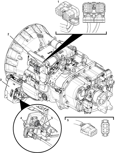 |
1. Transmission Electronic Control Unit (TECU) 2. 38-Way Transmission Harness Connector 3. ECA Shield 4. Electronic Clutch Actuator (ECA) 5. 8-Way ECA Connector |
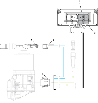 |
1. Transmission Electronic Control Unit (TECU) 2. 38-Way Transmission Harness Connector 3. 8-Way Gen2 ECA Connector 4. 2-Way Gen2 ECA Speed Sensor Connector Body 5. 2-Way Gen2 ECA Speed Sensor |
 |
Fault Code 65 Troubleshooting Gen2 ECA
Record the transmission fault codes, FMIs, occurrences, and timestamps from the Service Activity Report created during the Diagnostic Procedure.
Key on with engine off.
Connect ServiceRanger.
Update transmission and ECA software to latest available level, if not completed during the Diagnostic Procedure.
Notice
If Fault Code 56 with FMI 2 is Active, go to Fault Code Isolation Procedure Index.
If Fault Code 65 with FMI 3 is Active or Inactive, Go to Step B
If Fault Code 65 with FMI 2, 4 or 5 is Active or Inactive, Go to Step D
Key off.
Disconnect 8-Way Gen2 ECA Connector.
Inspect 8-Way Gen2 ECA Connector body for damage and bent, spread, corroded or loose terminals.
Measure resistance between 8-Way Gen2 ECA Connector Pin 3 and Pin 6. Record reading(s) in table based on configuration.
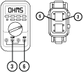
Measure resistance between 8-Way Gen2 ECA Connector Pin 6 and ground. Record reading(s) in table.
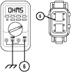
Compare reading(s) in table.
If readings are out of range, Go to Step C
If readings are in range, replace Electronic Clutch Actuator (ECA)Electronic Clutch Actuator (ECA). Go to Step V
| ECA Speed Sensor Configuration | Pins | Range | Reading(s) |
|---|---|---|---|
| Transmission Clutch Housing | 3 to 6 | 2.0k–4.5k Ohms | |
| Engine Flywheel Housing | 3 to 6 | 140–180 Ohms | |
| Both | 6 to ground | Open Circuit (OL) |
Key off.
Disconnect 2-Way Gen2 ECA Speed Sensor Connector.
Inspect 2-Way Connector body for damage and bent, spread, corroded or loose terminals.
Measure resistance between 2-Way Gen2 ECA Speed Sensor Connector Pin 1 and Pin 2. Record reading(s) in table based on configuration.
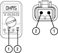
Measure resistance between 2-Way Gen2 ECA Speed Sensor Connector Pin 2 and ground. Record reading(s) in table.
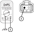
Compare reading(s) in table.
If readings are in range, replace Transmission Harness. Go to Step V
If readings are out of range, replace Electronic Clutch Actuator (ECA) Speed Sensor. Go to Step V
| ECA Speed Sensor Configuration | Pins | Range | Reading(s) |
|---|---|---|---|
| Transmission Clutch Housing | 1 to 2 | 2.0k–4.5k Ohms | |
| Engine Flywheel Housing | 1 to 2 | 140–180 Ohms | |
| Both | 2 to ground | Open Circuit (OL) |
Set vehicle parking brake and chock wheels.
Key on with engine on at idle.
Connect ServiceRanger.
Select “Data Monitor”.
Select “Speed”.
Select “Engine speed” and add parameter “Engine -190”.
Select “Transmission clutch input speed” and add parameter “Transmission - 5052”.
Monitor vehicle tachometer and record engine RPM value in table.
Monitor ServiceRanger and record “Engine speed” RPM value in table.
Monitor ServiceRanger and record “Transmission clutch input speed” RPM value in table.
NoticeCompare reading(s) in table.
If readings are out of range, Go to Step E
If readings are in range, Go to Step F
| Engine Speed Signal Source | Range | Reading(s) |
|---|---|---|
| Vehicle Tachometer | Idle RPM | |
| Parameter “Engine-190” | Within 150 RPM of Engine Idle RPM | |
| Parameter “Transmission- 5052” | Within 150 RPM of Engine Idle RPM |
Compare reading(s) recorded in Step D table.
If parameter “Engine - 190” RPM is out of range of Vehicle Tachometer Idle RPM, refer to OEM guidelines for repair or replacement of OEM Engine Speed Sensor signal. Go to Step V
If parameter “Transmission - 5052” RPM is out of range of Vehicle Tachometer Idle RPM, Go to Step H
Retrieve fault code(s) recorded in Step A.
If Fault Code 65 with FMI 2, 4 or 5 is Inactive, Go to Step G
If Fault Code 65 with FMI 2, 4 or 5 is Active, Go to Step H
Set parking brake and chock wheels.
Place transmission in PD Mode. See more about Product Diagnostic (PD) Mode.
Note: Transmission does not enter PD Mode when Active fault codes exist.

Wiggle wiring and connections of the Transmission Harness from the 2-Way Gen2 ECA Speed Sensor to the 8-Way Gen2 ECA Connector. Look for signs of pinched or chafed wiring. Verify all connections are clean and tight.
Exit PD Mode by powering down.
Notice
If any fault code sets Active while wiggling the Transmission Harness, replace Transmission Harness. Go to Step V
If any fault code sets Active while wiggling the ECA Speed Sensor wiring, replace Electronic Clutch Actuator (ECA) Speed Sensor. Go to Step V
If no fault code sets Active, Go to Step H
Key off.
Disconnect 8-Way Gen2 ECA Connector.
Inspect 8-Way Gen2 ECA Connector body for damage and bent, spread, corroded or loose terminals.
Measure resistance between 8-Way Gen2 ECA Connector Pin 3 and Pin 6. Record reading(s) in table based on configuration.

Measure resistance between 8-Way Gen2 ECA Connector Pin 6 and ground. Record reading(s) in table.

Compare reading(s) in table.
If readings are out of range, Go to Step I
If readings are in range, Go to Step J
| ECA Speed Sensor Configuration | Pins | Range | Reading(s) |
|---|---|---|---|
| Transmission Clutch Housing | 3 to 6 | 2.0k–4.5k Ohms | |
| Engine Flywheel Housing | 3 to 6 | 140–180 Ohms | |
| Both | 6 to ground | Open Circuit (OL) |
Key off.
Disconnect 2-Way Gen2 ECA Speed Sensor Connector.
Inspect 2-Way Connector body for damage and bent, spread, corroded or loose terminals.
Measure resistance between 2-Way Gen2 ECA Speed Sensor Connector Pin 1 and Pin 2. Record reading(s) in table based on configuration.

Measure resistance between 2-Way Gen2 ECA Speed Sensor Connector Pin 2 and ground. Record reading(s) in table.

Compare reading(s) in table.
If readings are in range, replace Transmission Harness. Go to Step V
If readings are out of range, replace Electronic Clutch Actuator (ECA) Speed Sensor. Go to Step V
| ECA Speed Sensor Configuration | Pins | Range | Reading(s) |
|---|---|---|---|
| Transmission Clutch Housing | 1 to 2 | 2.0k–4.5k Ohms | |
| Engine Flywheel Housing | 1 to 2 | 140–180 Ohms | |
| Both | 2 to ground | Open Circuit (OL) |
Inspect ECA Speed Sensor.
If equipped with Clutch Housing Push-In ECA Speed Sensor, Go to Step K
If equipped with Flywheel Housing Thread-In ECA Speed Sensor, Go to Step M
Key off.
Verify the Push-In ECA Speed Sensor is properly seated and installed in the Transmission Clutch Housing.
Remove ECA Speed Sensor. Inspect for signs of damage or debris build-up.
If no debris build-up or damage is present, Go to Step L
If sensor debris build-up or damage is found, inspect for cause of debris build-up or damage. Replace Electronic Clutch Actuator (ECA) Speed Sensor. Go to Step V
Key off.
Remove single bolt for clutch housing access cover.
Inspect Clutch Cover for any damaged or missing lugs.
If any damage is found or lugs are missing, replace the ECA Clutch. Go to Step V
If the Clutch Cover is not damaged and all lugs are present, replace Electronic Clutch Actuator (ECA). Go to Step V
Key off.
Verify the Thread-In ECA Speed Sensor is properly installed and adjusted in the Engine Flywheel Housing.
Note: Reference TRSM0930, Thread-In ECA Speed Sensor, Service Procedures.
Remove ECA Speed Sensor. Inspect for signs of debris build-up or damage.
If ECA Speed Sensor is properly installed and adjusted with no damage or debris build-up, Go to Step N
If ECA Speed Sensor is out of adjustment, perform thread-in ECA Speed Sensor adjustment. Go to Step V
If ECA Speed Sensor is damaged or debris build-up is evident, inspect for cause of damage or debris build-up. Replace Electronic Clutch Actuator (ECA) Speed Sensor. Go to Step V
Key off.
Inspect Engine Flywheel Ring Gear for debris, wear or damage.
If flywheel damage is found, refer to OEM guidelines for repair or replacement of Engine Flywheel. Go to Step V
If no flywheel damage is found, replace Electronic Clutch Actuator (ECA). Go to Step V
Key off.
Reconnect all connectors and verify that all components are properly installed.
Key on with engine off.
Clear fault codes using ServiceRanger.
Drive vehicle and attempt to reset the code or duplicate the previous complaint.
Check for fault codes using ServiceRanger.
If no fault codes set Active and vehicle operates properly, test complete.
If Fault Code 65 sets Active during the test drive, Go to Step A
If a fault code other than 65 sets Active, troubleshoot per Fault Code Isolation Procedure Index.