Fault Code 145: Secondary Shift Device (PWM)
J1939: SA 3 SPN 752 FMI 2, 4, 5, 8, 12, 13, 14
Overview
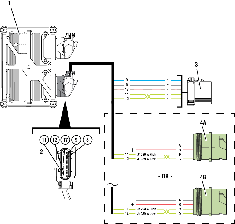
The Transmission Control Module (TCM) is configured to accept Primary Shift Device messages from the transmission driver interface device over the Primary Data Link (J1939A). This information is used to determine transmission operation. A Secondary Shift Device request signal from the transmission driver interface device is also provided on a separate hardwired circuit. The Secondary Shift Device request signal allows a driver to engage the transmission into a Shift Mode in the event the Primary Shift Device message is not available. The Primary Data Link (J1939A), transmission driver interface device, and Secondary Shift Device hardwired circuit and wiring are installed by the OEM and connect to the TCM through the 20-Way TCM Vehicle Harness Connector.
Note: Freightliner chassis (OEM Supplied Driver Interface Device) does not have a secondary shift device and must be configured (ACN 19) to J1939 CAN Device (w/o secondary).
Detection
The TCM monitors the Secondary Shift Device request signal. If the signal is not received or invalid, the fault is set Active.
Conditions to Set Fault Code Active
FMI 2 – Data Erratic: Secondary Shift Device request signal value out of range for 5 seconds.
FMI 4 – Voltage Below Normal or Shorted Low: Secondary Shift Device request circuit shorted to ground for 5 seconds.
FMI 5 – Current Below Normal or Open Circuit: Secondary Shift Device request circuit shorted to power or open for 5 seconds.
FMI 8 – Abnormal Frequency: Secondary Shift Device request signal frequency out of range for 5 seconds.
FMI 12 – Bad Intelligent Device: Inappropriate acceptance of non-Neutral Shift Mode without Service Brake depressed.
FMI 13 – Out of Calibration: Driver Interface Device incorrectly configured.
FMI 14 – Special Instructions: Delayed gear engagement after Shift Mode change.
Fallback
FMI 2, 4, 5, 8
- Amber warning lamp on
- No degraded performance
- If engine off and fault codes 135 and 145 are active:
- Engine cranking prohibited
- If engine running and fault codes 135 and 145 are active:
- Transmission stays in current gear
- PTO mode prohibited
- If vehicle is moving and fault codes 135 and 145 are active:
- Red stop lamp on
FMI 12:
- Amber warning lamp on
- Transmission stays in current gear
- PTO mode prohibited
- If vehicle is moving
- Red stop lamp on
FMI 13:
- Amber warning lamp on
- Engine cranking prohibited
FMI 14:
- Non neutral modes prohibited
- PTO mode prohibited
Conditions to Set Fault Code Inactive
FMI 2: Secondary Shift Device request signal in range for 10 seconds.
FMI 4: Secondary Shift Device request signal not shorted to ground for 10 seconds.
FMI 5: Secondary Shift Device request signal not shorted to power or open for 10 seconds.
FMI 8: Secondary Shift Device request signal frequency in range for 10 seconds.
FMI 12, 14: Key cycle and fault condition no longer exist.
FMI 13: Driver Interface Type properly configured in TCM or condition no longer exists.
Possible Causes
FMI 2, 5, 8:
- Vehicle Harness
- Wires shorted to power, shorted to ground, or open
- Terminals bent, spread, corroded or loose
- OEM Driver Interface Device
- Freightliner and Western Star incorrectly configured in TCM
- Internal Failure
- TCM
- Internal Failure
FMI 4:
- Fluid Pressure Sensor and/or Vehicle Harness
- Power supply shorted to ground (low)
- Vehicle Harness
- Wires shorted to power, shorted to ground, or open
- Terminals bent, spread, corroded or loose
- OEM Driver Interface Device
- Internal Failure
- TCM
- Internal Failure
FMI 12, 14:
- TCM
- Software Issue
- Internal Issue
FMI 13:
- TCM
- Driver Interface Device not configured
Component Identification
 |
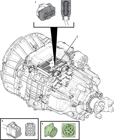
1. 20-Way TCM Vehicle Harness Connector 2. Transmission Control Module (TCM) 3. OEM Driver Interface Device Connector 4. 9-Way Type 2 Diagnostic Connector (In Cab) |
 |
1. Transmission Control Module (TCM) 2. 20-Way TCM Vehicle Harness Connector 3. OEM Driver Interface Device Connector 4. 9-Way Type 2 Diagnostic Connector - OEM Specific CD (in cab) 5. 9-Way Type 2 Diagnostic Connector - OEM Specific FG (in cab) *Refer to OEM wiring diagrams and connector views to verify circuit locations and descriptions |
 |
Fault Code 145 Troubleshooting
Set vehicle parking brake and chock wheels.
Record the transmission fault codes, FMIs, occurrences, and timestamps from the Service Activity Report created during the Diagnostic Procedure.
If Fault Code 145 is Inactive and there are other Active vehicle or transmission fault codes, troubleshoot all Active fault codes.Go to Step V
If Fault Code 145 FMI 4 and Fault Code 210 FMI 4 are both set Active or Inactive, troubleshoot per Fault Code 210: Transmission Oil Pressure (Fluid Pressure Sensor).
If Fault Code 145 FMI 5 is Inactive, Go to Step B
If Fault Code 145 FMI 5 is Active and OEM is Freightliner or Western Star, connect ServiceRanger, Go To Configuration, select Vehicle and configure Driver Interface Device to J1939 CAN Device w/o PWM (includes Freightliner and Western Star). Process complete.
If Fault Code 145 FMI 5 is Active in an OEM other than Freightliner, Go to Step B.
If Fault Code 145 FMI 2, 3, 4, 8 is Active or Inactive, Go to Step B
If Fault Code 145 FMI 13 is Active, configure Driver Interface Device using ServiceRanger. Test complete.
If Fault Code 145 FMI 13 is Inactive, Driver Interface Device is configured. Test complete.
If Fault Code 145 FMI 12 is Active or Inactive, Contact Eaton Cummins Automated Transmission Technologies for further diagnostic instructions. For Help Line phone numbers, go to Contact Information. Go to Step V
If Fault Code 145 FMI 14 is Active or Inactive, Go to Step E
Key off.
Disconnect the OEM Driver Interface Device Connector.
Inspect the OEM Driver Interface Device Connector, verify the connector is free from contamination and corrosion; the terminals are not bent, spread or loose; and there is no damage to the connector body.
Key on.
Measure voltage between OEM Driver Interface Connector (+) TCM supplied 12v and (-) TCM supplied ground. Record reading in table.

Compare reading(s) in table.
Note: Refer to OEM wiring diagrams and connector views to verify circuit locations and descriptions.
If readings are in range, Go to Step C
If readings are out of range, refer to OEM guidelines for repair or replacement of the Driver Interface Device power supply circuits between the OEM Driver Interface Device Connector and 20-Way TCM Vehicle Harness Connector. Go to Step V
| Pins | Range | Reading(s) |
|---|---|---|
| TCM supplied 12v to TCM supplied ground | 11–13 V |
Key off.
Disconnect 20-Way TCM Vehicle Harness Connector.
Inspect the 20-Way TCM Vehicle Harness Connector, verify the connector is free from contamination and corrosion; the terminals are not bent, spread or loose; and there is no damage to the connector body.
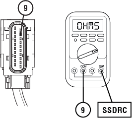
Measure resistance between the OEM Driver Interface Device Connector Secondary Shift Device Request Circuit (SSDRC) and 20-Way TCM Vehicle Harness Connector Pin 9. Record reading in table.

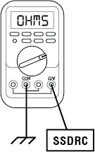
Measure resistance between the OEM Driver Interface Device Connector Secondary Shift Device Request Circuit (SSDRC) and Ground. Record reading in table.

Compare reading(s) in table.
Note: Refer to OEM wiring diagrams and connector views to verify circuit locations and descriptions.
If readings are in range, Go to Step D
If readings are out of range, refer to OEM guidelines for repair or replacement of the SSDRC between the OEM Driver Interface Device Connector and the 20-Way TCM Vehicle Harness Connector. Go to Step V
| Pins | Range | Reading(s) |
|---|---|---|
| SSDRC to 9 | 0.0 –0.3 Ohms | |
| SSDRC to Ground | Open Circuit (OL) |
Key off.
Reconnect all connectors and verify that all components are properly installed.
Key on.
Connect ServiceRanger.
Retrieve and record the transmission fault codes, FMIs, occurrences, and timestamps.
If Fault Code 145 is Active, refer to OEM guidelines for repair or replacement of the Driver Interface Device. Go to Step V
If Fault Code 145 is Inactive, no problem was found. The intermittent nature of the fault makes it likely that the problem is with the:
- Driver Interface Device
- Secondary shift device request circuit between the Driver Interface Device and 20-Way TCM Vehicle Harness Connector
- Power and ground supply wiring to the Driver Interface Device from the 20-Way TCM Vehicle Harness Connector
- Contact OEM for further diagnostic instructions.
Key off.
Allow TCM to perform a complete power down.
Key on with engine off.
Connect ServiceRanger.
Go to “Programming”.
Under “Software Information”, record TCM software in table.
If TCM software is less than 5516036, update TCM software to latest available version. Go to Step V
If TCM software is 5516036 or greater, contact Eaton Cummins Automated Transmission Technologies at 800-826-4357 for further diagnostic instructions. Go to Step V
Key off.
Reconnect all connectors and verify that all components are properly installed.
Key on with engine off.
Connect ServiceRanger.
Go to “Fault Codes”.
Select “Clear All Faults”.
Operate vehicle and attempt to reset the fault code or duplicate the previous complaint.
Check for fault codes using ServiceRanger.
If no fault codes set and the vehicle operates properly, test complete.
If Fault Code 145 sets Active during test drive, Go to Step A
If a fault code other than 145 sets Active, troubleshoot per the Fault Code Isolation Procedure Index.