Fault Code 215: Transmission Air Supply Pressure Sensor
J1939: SA 3 SPN 37 FMI 0, 1, 2, 3, 4, 5, 6, 10, 17, 18
Overview
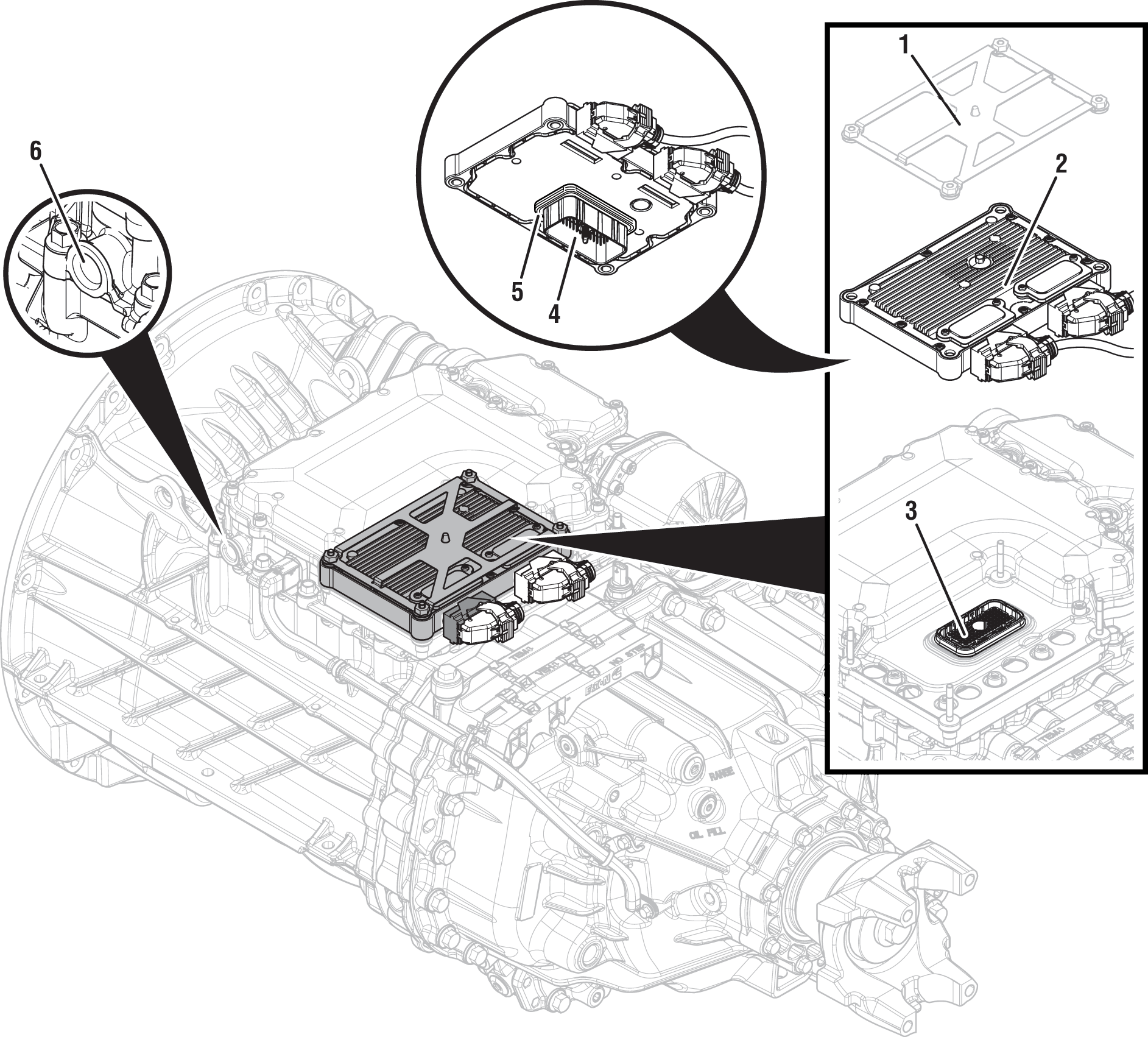
The Endurant XD Series transmissions are equipped with a Transmission Air Supply Pressure Sensor (TASPS) to monitor the air pressure supplied to the transmission. The TASPS connects into the vehicle air supply and provides a pressure input to the Transmission Control Module (TCM). The TCM monitors the pressure input to verify the transmission has the proper air pressure to actuate the clutch and shift rails. The TASPS is mounted in the Mechatronic Transmission Module (MTM) and connected to the TCM at the 74-way Transmission Harness Connector.
Note: The vehicle air supply comes from a dedicated transmission air tank. The primary and secondary air gauges in the cab of the vehicle may not reflect the pressure of the transmission air supply line. The transmission air tank is often isolated from the rest of the vehicle air system with a Pressure Protection Valve and/or Check Valve.
Detection
The TCM monitors the TASPS air pressure signal. If air pressure is outside of normal operating range or a system failure is detected, the fault is set Active.
Conditions to Set Fault Code Active
FMI 0 – Data Valid But Above Normal (Most Severe): Transmission air pressure greater than 145 psi (1000 kPa) for 1 second.
FMI 1 – Data Valid But Below Normal (Most Severe): Transmission air pressure less than 75 psi (517 kPa) for 1 second and one of the following is true:
- a non-Neutral mode is selected
- the vehicle is moving
- the engine has been running for 8 minutes
FMI 2 – Data Erratic: Transmission air pressure out of range, less than 5 psi (34.5 kPa) or greater than 203 psi (1400 kPa) for 5 seconds.
FMI 3 – Voltage Above Normal or Shorted High: TASPS circuit shorted to power for 5 seconds.
FMI 4 – Voltage Below Normal or Shorted Low: TASPS circuit shorted to ground for 5 seconds.
FMI 5 – Current Below Normal or Open Circuit: TASPS circuit open or shorted to ground for 5 seconds.
FMI 6 – Current Above Normal or Shorted Circuit: TASPS reference voltage out of range not between 4.75V to 5.25V for 5 seconds.
FMI 10 - Abnormal Rate of Change: TASPS value rate of change exceeded for 1 second.
FMI 17 – Data Valid but Below Normal (Least Severe): Transmission air pressure less than 75 psi (517 kPa) for 2 seconds with engine off and transmission shutdown in gear.
FMI 18 – Data Valid but Below Normal (Moderately Severe): Transmission air pressure less than 80 psi (552 kPa) for 2 seconds and one of the following is true:
- a non-Neutral mode is selected
- the vehicle is moving
- the engine has been running for 8 minutes
Fallback
FMI 0:
- Amber warning lamp on
- Urge to Move and Creep Mode prohibited
- Shift performance may be degraded
FMI 1:
- If transmission is in gear:
- Amber warning lamp on (OEM Specific)
- Coast Mode and Neutral Coast prohibited
- Urge to Move and Creep Mode prohibited
- Inertia Brake activation prohibited
- Upshifts prohibited
- Clutch engagements prohibited
- Non-Neutral modes prohibited
- PTO Mode prohibited
- If transmission is not in gear:
- Red stop lamp on (OEM specific)
- Clutch disengagements prohibited
FMI 2, 3, 4, 5, 6, 10, 17:
- Amber warning lamp on
- No degraded modes
FMI 18:
- Amber warning lamp on (OEM specific)
- Coast Mode and Neutral Coast prohibited
- Urge to Move and Creep Mode prohibited
- Inertia Brake activation prohibited
- Upshifts prohibited
- PTO Mode prohibited
Conditions to Set Fault Code Inactive
FMI 0: TASPS indicated air pressure below 145psi (1000 kPa) for 1 second.
FMI 1: TASPS indicated air pressure above 75psi (517 kPa) for 1 second.
FMI 2: TASPS indicated air pressure in range for 10 seconds.
FMI 3: TASPS circuit not shorted to power for 10 seconds.
FMI 4: TASPS circuit not shorted to ground for 10 seconds.
FMI 5: TASPS circuit not open or shorted to ground for 10 seconds.
FMI 6: TASPS reference voltage in range for 10 seconds.
FMI 10: Key cycle and fault condition no longer exists.
FMI 17: TASPS indicated air pressure above 75psi (517 kPa) and transmission in Neutral.
FMI 18: TASPS indicated air pressure above 80psi (552 kPa) for 1 second.
Possible Causes
FMI 0:
- Vehicle Components - Air System
- Air compressor governor “off” set too high or damaged
- Vehicle service event
- Connected to a Service facility air supply source
FMI 1, 18:
- Vehicle Components - Air System
- High system demand
- Air compressor governor “on” set too low or damaged
- Air compressor mechanically damaged
- Pressure Protection Valve stuck closed
- Air leak
- Internal transmission
- Air leak
FMI 2, 3, 4, 5, 6, 10:
- Transmission Air Supply Pressure Sensor
- Damaged
- Internal failure
- Transmission Air Supply Pressure Sensor Harness
- Wiring shorted to power, shorted to ground or open
- MTM Harness
- Wiring shorted to power, shorted to ground or open
- TCM
- Software issue
- Internal failure
FMI 17:
- Engine was shutdown when air supply pressure low and transmission still in gear
- Transmission service event
- Transmission mis-assembled in a gear position instead of a neutral position.
Additional Tools
- Endurant XD Service Manual TRSM0960
- Eaton Breakout Box with 74-Way Eaton Diagnostic Adapter - RR1029TR
- Digital Volt/Ohm Meter (DVOM)
- 0-200 psi (0-1379 kPa) air pressure gauge
Component Identification
 |
1. Transmission Control Module (TCM) Cover 2. Transmission Control Module (TCM) 3. 74-Way Transmission Harness Connector 4. TCM Side of 74-Way Transmission Harness Connector 5. Transmission Control Module (TCM) Seal 6. MTM Air Inlet Port |
Fault Code 215 Troubleshooting
Set vehicle parking brake and chock wheels.
Record transmission fault codes, FMIs, occurrences, and timestamps from Service Activity Report created during the Diagnostic Procedure.
If Fault Code 215 FMI 3, 4, 5, 6, 10 is Active or Inactive, Go to Step C
If Fault Code 215 FMI 0, 1, 2, 18 is Active or Inactive, Go to Step B
If Fault Code 215 FMI 17 is Active, connect an auxiliary air supply to the vehicle, air up the vehicle air system to 100-135 PSI (690-930 kPa) and key on. Go to Step V
If Fault Code 215 FMI 17 is Inactive, the transmission air supply pressure is in range and transmission is in Neutral. Go to Step V
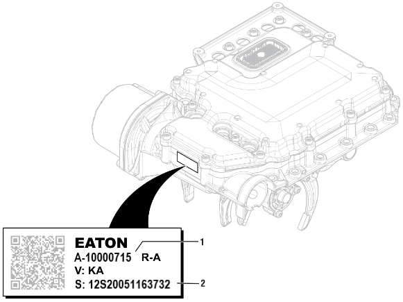
Record MTM Serial Number.

If MTM Serial Number is less than 18S25036075335, Contact Eaton Cummins Automated Transmission Technologies for further diagnostic instructions. For Help Line phone numbers, go to Contact Information.
If MTM Serial Number greater than or equal to 18S25036075335, Go to Step E
Key off.
Remove TCM from MTM with 20-Way TCM Vehicle Harness Connector and 20-Way TCM Body Harness Connector connected.

Inspect TCM side of the 74-Way Transmission Harness Connector, verify connector is free from contamination and corrosion; terminals are not bent, spread or loose; and there is no damage to connector body.
Inspect TCM Seal, verify seal is properly installed and there is no damage.
If contamination or damage is found, replace Transmission Control Module (TCM) and Mechatronic Transmission Module (MTM). Go to Step V
Note: MTM removal and installation requires transmission be removed from vehicle. Reference Endurant XD Service Manual TRSM0960, Transmission Removal Service Procedure.
If no contamination or damage is found, Go to Step D
Key off.
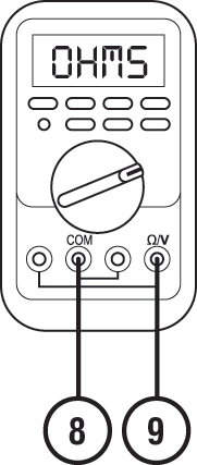
Connect Eaton Breakout Box with 74-Way Eaton Diagnostic Adapter to TCM 74-Way Connector.

Measure resistance at Eaton Breakout Box between Pin 8 and Pin 9. Record reading in table.

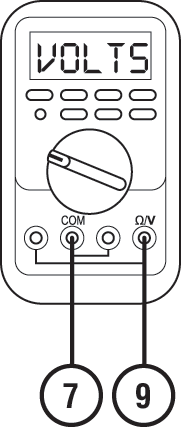
Key on.
Measure voltage at Eaton Breakout Box between Pin 7 and Pin 9. Record reading in table.

Compare reading(s) in table.
If readings are in range, replace Mechatronic Transmission Module (MTM). Go to Step V
Note: MTM removal and installation requires transmission be removed from vehicle. Reference Endurant XD Service Manual TRSM0960, Transmission Removal Service Procedure.
If readings are out of range, replace Transmission Control Module (TCM). Go to Step V
| Ignition State | Pins | Range | Reading(s) |
|---|---|---|---|
| Key off | 8 to 9 | 3k-9k Ohms | |
| Key on | 7 to 9 | 4.75–5.25 V |
Key on with engine running.
Allow air pressure to build to governor cut off.
Key off.
Key on with engine off.
Connect ServiceRanger.
Go To “Data Monitor”.
From the “Default Parameter Files” tab, select “Transmission Pressure”.
Monitor 520524 - Line Pressure Feedback value. Record reading in table.
Monitor vehicle in-dash air pressure gauge. Record reading in table.
Wait 1 minute.
Monitor 520524 - Line Pressure Feedback value. Record reading in table.
Monitor vehicle in-dash air pressure gauge. Record reading in table.
Compare reading(s) in table.
If readings are out of range and/or system cannot hold pressure, Go to Step F
If readings are in range and the vehicle air system holds pressure and FMI 1 or 18 are Inactive, refer to service bulletin TAIB-0876 in the TRIB-0900. Go to Step V
If readings are in range and FMI 0 is Inactive, refer to OEM guidelines and verify operation and maintenance of the vehicle air system. Go to Step V
If reading are in range and FMI 2 is Inactive, Go to Step C
If readings are in range, the vehicle air system holds pressure and FMI 0, 1, 2 or 18 are Active, replace Mechatronic Transmission Module (MTM). Go to Step V
Note: MTM removal and installation requires transmission be removed from vehicle. Reference Endurant XD Service Manual TRSM0960, Transmission Removal Service Procedure.
| Source | Range | Reading(s) |
|---|---|---|
| In-dash air pressure gauge | 100–135 PSI (690-930 kPa) | |
| 520524 - Line Pressure Feedback | 100–135 PSI (690-930 kPa) | |
| After 1 minute | ||
| In-dash air pressure gauge | 100–135 PSI (690-930 kPa) | |
| 520524 - Line Pressure Feedback | 100–135 PSI (690-930 kPa) | |
Refer to OEM guidelines and vent vehicle air supply line to MTM.
Refer to OEM guidelines and remove vehicle air supply line at MTM.
Inspect vehicle air supply line and MTM air inlet port for contamination, moisture, corrosion and/or debris.
Note: Verify MTM inlet screen is installed and free of contamination and/or debris.

If contamination is found, refer to OEM guideline for repair or replacement of vehicle air system. Replace Mechatronic Transmission Module (MTM) and reference Lower Countershaft Cover and Inertia Brake Service Procedure for replacement of the Inertia Brake Assembly. Go to Step V
Note: MTM removal and installation requires transmission be removed from vehicle. Reference Endurant XD Service Manual TRSM0960, Transmission Removal Service Procedure.
If no contamination is found, Go to Step G
Key off.
Install a 0-200 PSI air pressure gauge on the vehicle air supply line at the MTM.
Key on with engine running.
Allow air pressure to build to governor cut off.
Key off.
Monitor air pressure gauge installed in the vehicle air supply line and record reading in table.
Wait 1 minute.
Monitor air pressure gauge installed in the vehicle air supply line and record reading in table.
Compare reading(s) in table.
If readings are out of range or the vehicle air system cannot hold pressure, refer to OEM guidelines for repair or replacement of vehicle air system. Go to Step V
If readings are in range, replace Mechatronic Transmission Module (MTM). Go to Step V
Note: MTM removal and installation requires transmission be removed from vehicle. Reference Endurant XD Service Manual TRSM0960, Transmission Removal Service Procedure.
| Source | Range | Reading(s) |
|---|---|---|
| Air pressure gauge | 100–135 PSI (690-930 kPa) | |
| After 1 Minute | ||
| Air pressure gauge | 100–135 PSI (690-930 kPa) | |
Key off.
Reconnect all connectors and verify all components are properly installed.
Key on with engine off.
Connect ServiceRanger.
Go To “Fault Codes”.
Select “Clear All Faults”.
Operate vehicle and attempt to reset the fault code or duplicate the previous complaint.
Check for fault codes using ServiceRanger.
If no fault codes set and vehicle operates properly, test complete.
If Fault Code 215 sets Active, Go to Step A
If a fault code other than 215 sets Active, troubleshoot per Fault Code Isolation Procedure Index.