Fault Code 67: Gen1 ECA Ignition Voltage
J1587: MID 130 PID 158 FMI 3, 4
J1939: SA 3 SPN 520274 FMI 3, 4
Overview
The UltraShift PLUS transmission is equipped with an Electronic Clutch Actuator (ECA) that controls the position of the clutch assembly. The ECA requires a 12-volt ignition supply from the Transmission Electronic Control Unit (TECU) via the Transmission Harness to initiate ECA operation when the key is on. Fault Code 67 indicates an issue with the ignition supply voltage to the ECA.
Detection
After power up, the ECA monitors the ignition voltage from the TECU. If the ECA loses ignition voltage, but maintains battery voltage and High Integrity Link (HIL) communication, that information is broadcast to the TECU and the fault code sets Active.
Conditions to Set Fault Code Active
FMI 3 – Voltage Above Normal or Shorted High: ECA ignition voltage is shorted high for 2 seconds during key on operation.
FMI 4 – Voltage Below Normal or Shorted Low: ECA ignition voltage is shorted to ground or open for 2 seconds or longer during key on operation.
Fallback
All FMIs:
- “F” flashes in gear display.
- Service light flashes (if equipped).
- Engine does crank but the transmission cannot engage a start gear from neutral.
- If failure occurs during operation transmission shift quality is not affected by the fault until the vehicle ignition switch is turned off and TECU powers down.
Conditions to Set Fault Code Inactive
All FMIs: Ignition voltage signal is within range for 6 seconds.
Possible Causes
All FMIs:
- Transmission Harness
- Damage to wiring between the TECU and ECA
- Bent, spread, corroded or loose terminals
- Wiring shorted to ground or open
- ECA
- Internal failure
- TECU
- Internal failure
- Vehicle Harness
- Wiring shorted to ground or shorted to power
Component Identification
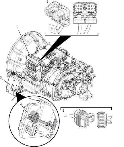 |
1. Transmission Electronic Control Unit (TECU) 2. 38-Way Transmission Harness Connector 3. Gen1 ECA Shield 4. Gen1 Electronic Clutch Actuator (ECA) 5. 8-Way Gen1 ECA Connector |
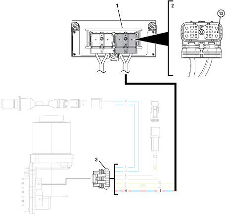 |
1. Transmission Electronic Control Unit (TECU) 2. 38-Way Transmission Harness Connector 3. 8-Way Gen1 ECA Connector |
 |
Fault Code 67 Troubleshooting Gen1 ECA
Inspect ECA OEM Power Supply Connector, reference image below.

If equipped with a Gen1 ECA, Go to Step B
If equipped with a Gen2 ECA, go to Fault Code 67: Gen2 ECA Ignition Voltage.
Determine if vehicle manufacturer is PACCAR.
If vehicle is not manufactured by PACCAR, Go to Step C
If vehicle is manufactured by PACCAR, Go to Step J
Record the transmission fault codes, FMIs, occurrences, and timestamps from the Service Activity Report created during the Diagnostic Procedure.
If Fault Code 67 is Active, Go to Step D
If Fault Code 67 is Inactive, replace the Transmission Harness. Go to Step V
Set parking brake and chock wheels.
Key off.
Disconnect the 8-Way Gen1 ECA Connector.
Verify the connector is free from contamination and corrosion; the terminals are not bent, spread or loose; and there is no damage to the connector body.
Inspect the ECA side of the 8-Way Gen1 ECA Connector, verify the connector is free from contamination and corrosion; the terminals are not bent, spread or loose; and there is no damage to the connector body.
If no contamination and damage is found, Go to Step E
If contamination or damage is found, replace the Electronic Clutch Actuator (ECA) and Transmission Harness. Go to Step V
Key on.
Measure voltage between 8-Way Gen1 ECA Connector Pin H and ground. Record reading(s) in table.
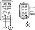
Compare reading(s) in table.
Note: If ECA is replaced, perform clutch adjustment through ServiceRanger prior to vehicle operation.
If readings are in range, Go to Step F
If readings are out of range, Go to Step G
| Pins | Range | Reading(s) |
|---|---|---|
| H to Ground | Within 1.2 V of Battery Voltage |
Key off.
Reconnect the 8-Way Gen1 ECA Connector and verify that all components are properly installed.
Key on.
Connect ServiceRanger.
Retrieve and record the transmission fault codes and FMIs and their occurrences and timestamps.
If Fault Code 67 is Active, replace the Electronic Clutch Actuator (ECA). Go to Step V
If Fault Code 67 is Inactive, replace the Transmission Harness. Go to Step V
Key off.
Disconnect 38-Way Transmission Harness Connector.
Verify the connector is free from contamination and corrosion; the terminals are not bent, spread or loose; and there is no damage to the connector body.
Measure resistance between 38-Way Transmission Harness Connector Pin 13 and 8-Way Gen1 ECA Connector Pin H. Record reading(s) in table.
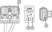
Compare reading(s) in table.
If readings are in range, Go to Step H
If readings are out of range, replace Transmission Harness. Go to Step V
| Pins | Range | Reading(s) |
|---|---|---|
| 13 to H | 0.0–0.5 ohms |
Key off.
Measure resistance between 38-Way Transmission Harness Connector Pin 13 and ground. Record reading(s) in table.
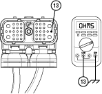
Compare reading(s) in table.
If readings are out of range, replace the Transmission Harness. Go to Step V
If readings are in range, Go to Step I
| Pins | Range | Reading(s) |
|---|---|---|
| 13 to Ground | Open Circuit (OL) |
Key off.
Reconnect all connectors and verify that all components are properly installed.
Key on.
Connect ServiceRanger.
Retrieve and record the transmission fault codes and FMIs and their occurrences and timestamps.
If Fault Code 67 is Active, replace the Transmission Electronic Control Unit (TECU). Go to Step V
If Fault Code 67 is Inactive, replace the Transmission Harness. Go to Step V
Refer to TAIB-0883.
If TAIB-0883 has not been completed, perform TAIB-0883.
If vehicle does not meet criteria of TAIB-0883 or if TAIB-0883 was already completed, Go to Step C
Key off.
Reconnect all connectors and verify that all components are properly installed.
Key on with engine off.
Clear fault codes using ServiceRanger.
Drive vehicle and attempt to reset the code or duplicate the previous complaint.
Check for fault codes using ServiceRanger.
If no fault codes set Active and vehicle operates properly, test complete.
If Fault Code 67 sets Active during the test drive, Go to Step A
If a fault code other than 67 sets Active, see the Fault Code Isolation Procedure Index.