Fault Code 71: Unable to Disengage Gear
J1587: MID 130 SID 60 FMI 7, 11
J1939: SA 3 SPN 560 FMI 7, 11
Overview
The UltraShift PLUS transmission uses the X-Y Shifter to engage and disengage a gear based on the driver’s selected mode of operation. Gear disengagement is achieved by activating the X-Y Shifter Gear Motor, which controls the fore-and-aft movement of the Shift Finger. Pushing the Shift Finger against one of the Shift Bar Housing Shift Blocks guides the Shift Yoke to disengage the Sliding Clutch from a gear. The position of the X-Y Shift Finger is monitored by the Transmission Electronic Control Unit (TECU) by way of the X-Y Gear Position Sensor and Rail Position Sensor.
Fault Code 71 is set when the X-Y Shift Finger attempts to pull out of gear, but the X-Y Gear Position Sensor indicates that the transmission was unable to disengage that gear. The TECU detected a system failure, but was unable to detect the specific root cause.
Detection
This fault can only be detected when there are no failures of the TECU, X-Y Gear or Rail Motors, X-Y Position Sensors or Battery Supply voltage. This fault code is set when the system is unable to pull the transmission out of gear.
Conditions to Set Fault Code Active
FMI 7 – Mechanical System Not Responding: After the first failed attempt to pull to neutral, the system opens the clutch to break torque and attempts to pull to neutral again. If the system is unable to achieve neutral after three consecutive attempts, the fault code sets Active.
FMI 11 – Root Cause Unknown: When the engine is running and the vehicle comes to a complete stop, the system opens the clutch. If neutral is requested or commanded, the system attempts to shift to neutral. If the system is unable to achieve neutral after 4 seconds, the fault code sets Active. The system will continue to attempt to pull to neutral for 2 seconds. If the system is unable to obtain neutral, the system requests the engine to shut down.
Fallback
FMI 7
- Transmission may not be able to complete a shift to neutral.
- Transmission will attempt to move the Shift Finger to neutral.
- Engine may not crank.
- Gear display may flash current or destination gear.
- Until the fault becomes Inactive, driver may have to shut off engine with transmission in gear.
FMI 11
- “F” flashes in gear display.
- Service light flashes (if equipped).
- Engine may shut down (if engine shutdown message is supported by the Engine).
- Engine may be shut down with transmission in gear.
- If neutral was achieved, Low range gears are available (if engine shutdown message is not supported by the Engine).
- Engine may not crank if the transmission cannot shift to neutral.
Conditions to Set Fault Code Inactive
FMI 7: The system successfully completes a shift into Neutral.
FMI 11: Refer to troubleshooting steps.
Possible Causes
FMI 7
- Vehicle Power Supply
- Poor power or ground supply to TECU
- Bent, spread, corroded or loose terminals
- Vehicle Batteries
- Internal failure
- Transmission Harness
- Damaged wiring between the TECU and X-Y Shifter
- Bent, spread, corroded or loose terminals
- X-Y Shifter
- Worn or damaged X-Y Shifter ball screw, center shaft bushing, or other internal components
- Contamination of X-Y Shifter ball screw due to coolant leak or oil contamination
- Bent, spread, corroded or loose terminals
- Mechanical Transmission
- Worn or damaged Shift Bar Housing
- Worn or damaged Sliding Clutch slot width
- Worn or damaged Shift Yokes
- Worn or damaged internal transmission components
- Clutch
- Not properly disengaging (clutch drag)
FMI 11
- Refer to troubleshooting steps.
Component Identification
 |
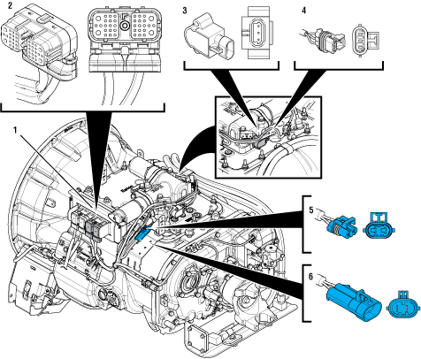
1. Transmission Electronic Control Unit (TECU) 2. 38-Way Transmission Harness Connector 3. Gear Position Sensor 4. 3-Way Gear Position Sensor Connector 5. 2-Way Gear Motor Connector (blue) 6. 2-Way Gear Motor Connector Body (blue) |
 |
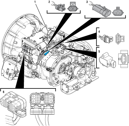
1. X-Y Shifter 2. 2-Way Rail Motor Connector (black) 3. 2-Way Rail Motor Connector Body (black) 4. 3-Way Rail Position Sensor Connector 5. Rail Position Sensor 6. 38-Way Vehicle Harness Connector |
Fault Code 71 Troubleshooting
Set vehicle parking brake and chock wheels.
Record the transmission fault codes, FMIs, occurrences, and timestamps from the Service Activity Report created during the Diagnostic Procedure.
Note: If Fault Code 71 FMI 7 is Inactive and there are other Active fault codes, troubleshoot all Active fault codes first.
If Fault Code 71 FMI 11 is Active, Go to Step I
If Fault Code 71 FMI 11 is Inactive, Go to Step V
If Fault Code 71 FMI 7 is Active or Inactive and/or Fault Codes 27, 33, 34, 51, 52, 61, 63 or 64 are Active or Inactive, troubleshoot per Fault Code Isolation Procedure Index.
If Fault Code 71 FMI 7 is Inactive, Go to Step B
If Fault Code 71 FMI 7 is Active, Go to Step C
Set parking brake and chock wheels.
Place transmission in PD Mode. See more about Product Diagnostic (PD) Mode.
Note: Fault Code 71 does not set Active during PD Mode. Other fault codes may set Active during PD Mode that could indicate an issue with the wiring.
Note: Transmission does not enter PD Mode when Active fault codes exist.

Wiggle wiring and connections of the Transmission Harness from the X-Y Shifter to the TECU.
Wiggle wiring and connections of the Vehicle Power Supply Harness from the batteries to the TECU.
Exit PD Mode by powering down.
Notice
If any fault sets Active while wiggling the Transmission Harness, replace Transmission Harness. Go to Step V
If any fault sets Active while wiggling the Power Supply harness, refer to OEM guidelines for repair or replacement of Power Supply wiring. Go to Step V
If no fault codes set Active, Go to Step C
Key off.
NoticeInspect Starter, battery terminals and transmission 30-amp In-line Fuse Holder Connections for corrosion, loose terminals and bent or spread pins.
Inspect Battery Positive (+) and Negative (-) wires from the batteries to the TECU including all connections. Ensure a clean ground connection on the chassis. Verify no damage or corrosion to connectors.
If damage is found, repair or replace Power Supply Harness per OEM guidelines. Go to Step V
If no damage is found, Go to Step D
Key off.
Set parking brake and chock wheels.
Load test each vehicle battery per OEM specifications. Record reading(s).
If any battery does not pass the Load Test, refer to OEM guidelines for repair or replacement of batteries. Go to Step V
If all batteries pass the Load Test, Go to Step E
| Battery | Voltage Drop | Load Test Status (Pass/Fail) |
|---|---|---|
| 1 | ||
| 2 | ||
| 3 | ||
| 4 | ||
| 5 |
Key off.
NoticeInspect the physical condition of X-Y Shifter and all connections.
Inspect Transmission Harness for any pinched, chafed, corroded or shorted wiring.
Disconnect both 2-Way X-Y Gear and Rail Position Sensor Connectors.

Disconnect both 2-Way X-Y Motor Connectors to the Transmission Harness.
Inspect connectors for corrosion, loose terminals, bent or spread pin or damage to the connector bodies.
If damage to the X-Y Shifter or X-Y Shifter wiring is found, replace X-Y Shifter. Go to Step V
If damage to the Transmission Harness is found, replace Transmission Harness. Go to Step V
If no damage is found, Go to Step F
Key off.
Remove the X-Y Shifter.
Inspect condition of the X-Y Shift Finger and Cross Shaft for damage or wear.

Inspect the X-Y Shifter ball screw for signs of coolant contamination.
For the latest Service Bulletin updates, visit Roadranger.com.
If coolant contamination is found, repair the vehicle coolant system leak and follow Service Bulletin TMIB0124 for complete repair procedure. X-Y Shifter must be replaced upon completion of service bulletin. Go to Step V
If damage to the X-Y Shifter is found, replace X-Y Shifter. Go to Step V
If no damage is found, Go to Step G
Key off.
Inspect condition of the Shift Bar Housing Shift Blocks. Look for uneven gaps between the Shift Blocks or excessive wear to the block faces.
Verify Shift Blocks are tight to the rails and there are no other mechanical issues with the Shift Bar Housing.

Verify transmission shifts fully in and out of each gear.
Test the Shift Interlock to verify that the transmission will not engage two gears at once. See the Shift Interlock Inspection Procedure Shift Interlock Inspection.
If damage to the Shift Bar Housing is found, repair Shift Bar Housing. Go to Step V
If no damage is found, Go to Step H
Key off.
Drain and save the transmission oil. Inspect oil for significant metal fragments.
Remove 8-bolt PTO cover.
Inspect main case gears for damage or excessive movement.
Inspect Shift Yokes and Sliding Clutches for damage or excessive wear.
If damage is found or there are significant metal fragments in the oil, replace damaged, worn or failed transmission components. Go to Step V
If no damage is found within the transmission main case, replace X-Y Shifter and Transmission Harness. Go to Step V
Note: If unsure whether damage or wear is significant, take pictures of the transmission gearing. Ensure these pictures are clear and the components are easily visible. Email these pictures to auto.rtw@eaton.com and contact Eaton at (800) 826-4357.
Refer to RRMT0019.
Clear Fault Code 71 FMI 11 per RRMT0019. Go to Step J
Key on with engine off.
Connect ServiceRanger.
Go To Programming.
Under "Software Information", record TECU software version.
If TECU software is less than 5570064, update TECU software to 5570064 or greater. Go to Step K
If TECU software is 5570064 or greater, Go to Step K
Key Off.
Set vehicle parking brake and chock wheels.
Go to Service Bulletin CLIB0035.
Review and follow steps outlined in Service Bulletin CLIB0035, Go to Step V
Key off.
Reconnect all connectors and verify that all components are properly installed, including X-Y Shifter.
Reinstall 8-bolt PTO cover.
Refill transmission with lubricant.
Key on with engine off.
Clear fault codes using ServiceRanger.
Drive vehicle and attempt to reset the code or duplicate the previous complaint.
Check for fault codes using ServiceRanger.
If no fault codes set Active and vehicle operates properly, test complete.
If a fault code other than 71 sets Active, troubleshoot per Fault Code Isolation Procedure Index.
If Fault Code 71 sets Active, refer to Contact Information and contact Eaton for further diagnostics.