Fault Code 511: Clutch Engage Solenoid 1 (C4) – Coarse Vent
J1939: SA 3 SPN 5614 FMI 0, 1, 3, 4, 5, 6, 7, 8, 10, 12, 16, 18
Overview
The Endurant HD transmission is equipped with solenoids to direct pneumatic flow to release and engage the clutch. The Clutch Engage Solenoid 1 (CES1) is energized by the Transmission Control Module (TCM) to exhaust air pressure from the Linear Clutch Actuator (LCA) and engage the clutch. The clutch control system requires four solenoids to control the clutch position – two clutch engage solenoids and two clutch release solenoids. The CES1 quickly exhausts air pressure from the LCA to engage the clutch. The CES1 is located in the Mechatronic Transmission Module (MTM) and connected to the TCM at the 74-Way Transmission Harness Connector.
Detection
The TCM monitors the CES1. If a system failure is detected, the fault is set Active.
Conditions to Set Fault Code Active
FMI 0 – Data Valid But Above Normal (Most Severe): CES1 low side current is greater than commanded current.
FMI 1 – Data Valid But Below Normal (Most Severe): CES1 low side current is less than commanded current.
FMI 3 – Voltage Above Normal or Shorted High: CES1 shorted to power for 2 seconds.
FMI 4 – Voltage Below Normal or Shorted Low: CES1 commanded off and shorted to ground for 2 seconds.
FMI 5 – Current Below Normal or Open Circuit: CES1 open circuit for 2 seconds.
FMI 6 – Current Above Normal or Shorted Circuit: CES1 commanded on and shorted to ground.
FMI 7 – Mechanical System Not Responding: The LCA Position Sensor reports the clutch is engaged while the clutch control system is attempting to release the clutch.
FMI 8 – Abnormal Frequency: CES1 out of normal operating frequency for 4 seconds.
FMI 10 – Abnormal Rate of Change: The clutch release solenoid has been commanded on for a longer duty cycle than expected to maintain clutch release.
FMI 12 – Bad Intelligent Device: CES1 commanded on beyond expected duty cycle.
FMI 16 – Data Valid but Above Normal (Moderately Severe): CES1 commanded on for longer than expected increasing solenoid temperature.
FMI 18 – Data Valid but Below Normal (Moderately Severe): CES1 commanded on below expected voltage.
Fallback
FMI 0, 1, 5, 6, 8, 12, 16, 18:
- Amber warning lamp on
- Clutch Engage Solenoid 1 operation prohibited
- May experience slow clutch engagement
FMI 3, 4:
- Amber warning lamp on
- Clutch Engage Solenoid 1 operation prohibited
- Clutch Release Solenoid 2 operation prohibited
- Urge to Move and Creep mode prohibited
- Raised shift points
FMI 7, 10:
- Amber warning lamp on
- Non-Neutral modes prohibited
- PTO mode prohibited
- If transmission is in gear and moving
- Red stop lamp on
- Urge to Move and Creep Mode prohibited
- Upshifts prohibited
- Raised shift points
- Engine may shut down
Conditions to Set Fault Code Inactive
FMI 0, 1, 6, 7, 8, 10, 12, 16, 18: Key cycle
FMI 3, 4, 5, 8: CES1 in range for 10 seconds
Possible Causes
FMI 0, 1, 3, 4, 5, 6, 8, 18
- MTM – Clutch Engage Solenoid 1
- Internal failure
- Damaged
- MTM - Transmission Harness
- Wiring shorted to power, shorted to ground or open
- TCM
- Internal failure
FMI 7:
- LCA
- Stuck piston
- LCA to MTM seal air leak
- Internal failure
- MTM – Clutch Engage Solenoid 1 and/or 2
- Stuck open
- Air leak
- Clutch Housing
- Damaged Release Bearing
- Damaged Front Bearing Cover
- Damaged Release Yoke
- Damaged Clutch
- TCM
- Software issue
FMI 10:
- MTM – Clutch Engage Solenoid 1 and/or 2
- Stuck open
- Air leak
- TCM
- Software issue
- LCA
- Internal failure
FMI 12:
- TCM
- Software issue
- Internal failure
FMI 16
- LCA
- Stuck piston
- LCA to MTM seal air leak
- Internal failure
- MTM – Clutch Engage Solenoid 1 and/or 2
- Stuck open
- Air leak
- Clutch Housing
- Damaged Release Bearing
- Damaged Front Bearing Cover
- Damaged Release Yoke
- Damaged Clutch
Additional Tools
- Endurant HD Service Manual TRSM0950
- Eaton Breakout Box with 74-Way Eaton Diagnostic Adapter - RR1029TR
- Digital Volt/Ohm Meter (DVOM)
Component Identification
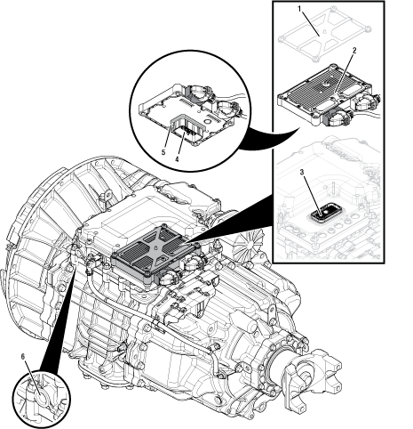 |
1. Transmission Control Module (TCM) Cover 2. Transmission Control Module (TCM) 3. 74-Way Transmission Harness Connector (MTM-side) 4. 74-Way Transmission Harness Connector (TCM-side) 5. Transmission Control Module (TCM) Seal 6. MTM Air Inlet Port |
Fault Code 511 Troubleshooting
Set vehicle parking brake and chock wheels.
Record the transmission fault codes, FMIs, occurrences, and timestamps from the Service Activity report created during the Diagnostic Procedure.
If Fault Code 511 FMI 0, 1, 3, 4, 5, 6, 8, 18 is Active or Inactive, Go to Step B
If Fault Code 511 FMI 7 or 10 is Active or Inactive, Refer to Service Bulletin TAIB-0885. Go to Step V
If Fault Code 511 FMI 12 or 16 is Active or Inactive, Contact Eaton Cummins Automated Transmission Technologies for further diagnostic instructions. For Help Line phone numbers, go to Contact Information. Go to Step V
Key off.
Remove the TCM from the MTM with the 20-Way TCM Vehicle Harness Connector and 20-Way TCM Body Harness Connector connected.

Inspect the TCM side of the 74-Way Transmission Harness Connector, verify the connector is free from contamination and corrosion; the terminals are not bent, spread or loose; and there is no damage to the connector body.
Inspect the TCM Seal, verify the seal is properly installed and not damaged.
If contamination or damage is found to the TCM side of the 74-Way Transmission Harness Connector, replace the Transmission Control Module (TCM) and Mechatronic Transmission Module (MTM). Go to Step V
Note: MTM removal and installation requires the transmission to be removed from the vehicle. Reference Endurant HD Service Manual TRSM0950, Transmission Removal Service Procedure.
If no contamination or damage is found, Go to Step C
Key on with engine off.
Connect ServiceRanger.
Go To “Configuration”.
Select “Advanced”.
Note: If “Advanced” is not indicated, TCM software is unable to determine MTM Type. Go to Step 6.
Record “MTM Type” Current Value, go to Step 7.
Locate MTM part information tag and record MTM Part Number (Item 1) in table.
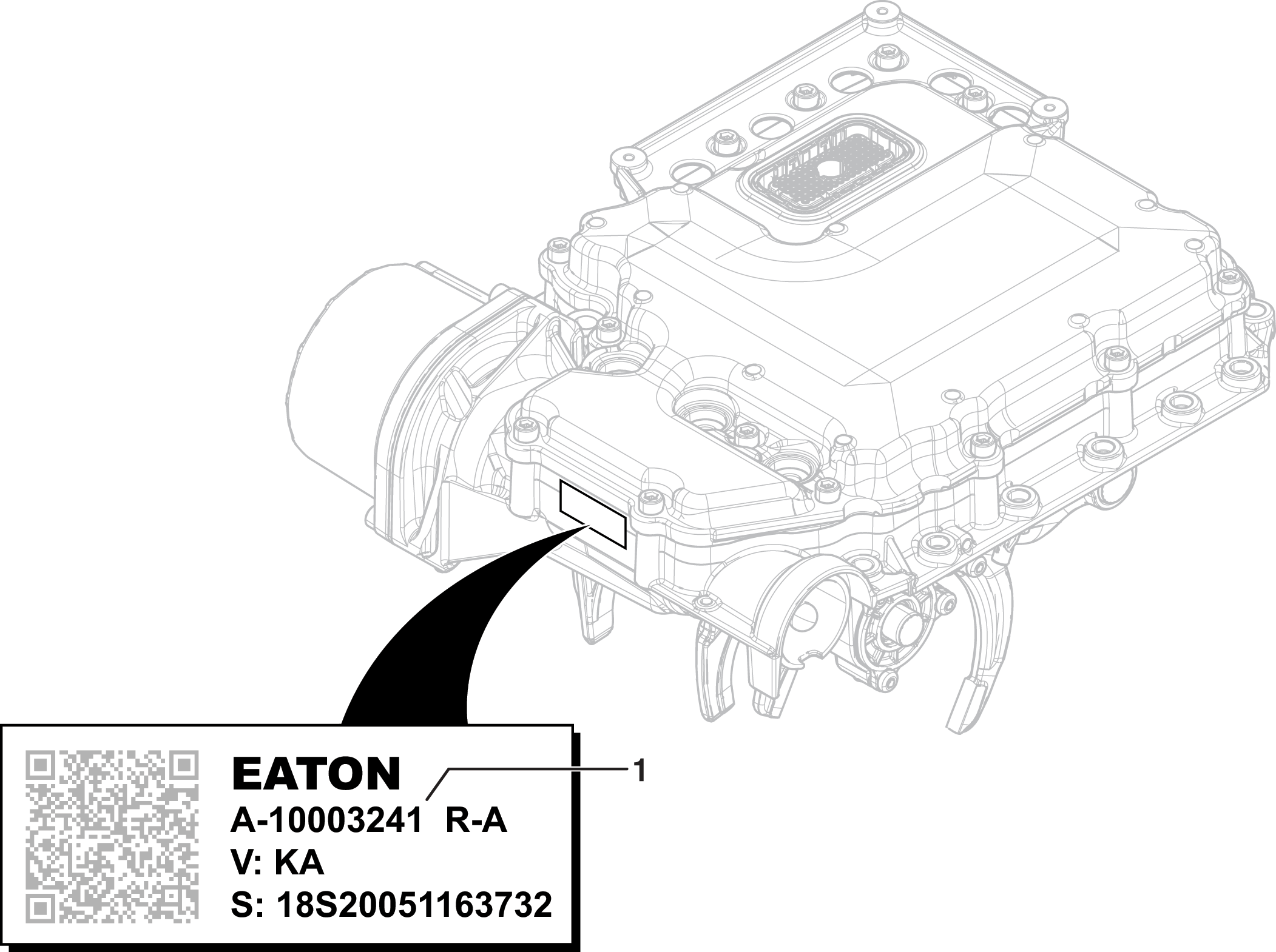
Compare MTM Part Number recorded in Step 6 with MTM Part Number in table to determine MTM Type.
If MTM Type is PS-393, Go to Step D
If MTM Type is PS-496, Go to Step E
| MTM Part Number on tag | |
|---|---|
| MTM Part Number | MTM Type |
| A-10000715 | PS-393 |
| A-10002594 | |
| A-10004202 | |
| A-10004231 | PS-496 |
| A-10004356 | |
| A-10004383 | |
Key off.
Connect the Eaton Breakout Box with 74-Way Eaton Diagnostic Adapter to the MTM side of the 74-Way Transmission Harness Connector.
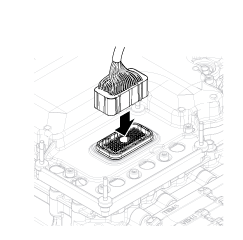
Measure resistance at the Eaton Breakout Box between Pin 18 and Pin 19. Record reading in table.

Measure resistance at the Eaton Breakout Box between Pin 19 and Ground (TCM mounting stud). Record reading in table.

Compare reading(s) in table.
If readings are in range, Go to Step F
If readings are out of range, replace the Mechatronic Transmission Module (MTM). Go to Step V
Note: MTM removal and installation requires the transmission to be removed from the vehicle. Reference Endurant HD Service Manual TRSM0950, Transmission Removal Service Procedure.
| Pins | Range | Reading(s) |
|---|---|---|
| 18 to 19 | 2.5–3.1 Ohms | |
| 19 to ground (TCM mounting stud) | Open Circuit (OL) |
Key off.
Connect the Eaton Breakout Box with 74-Way Eaton Diagnostic Adapter to the MTM side of the 74-Way Transmission Harness Connector.

Measure resistance at the Eaton Breakout Box between Pin 30 and Pin 31. Record reading in table.
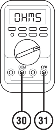
Measure resistance at the Eaton Breakout Box between Pin 30 and Ground (TCM mounting stud). Record reading in table.
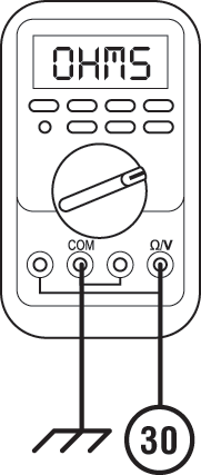
Compare reading(s) in table.
If readings are in range, Go to Step F
If readings are out of range, replace the Mechatronic Transmission Module (MTM). Go to Step V
Note: MTM removal and installation requires the transmission to be removed from the vehicle. Reference Endurant HD Service Manual TRSM0950, Transmission Removal Service Procedure.
| Pins | Range | Reading(s) |
|---|---|---|
| 30 to 31 | 2.3–3.9 Ohms | |
| 30 to ground (TCM mounting stud) | Open Circuit (OL) |
Key off.
Remove the 74-Way Eaton Diagnostic Adapter.
Reinstall the TCM to the MTM.
Reconnect all connectors and verify that all components are properly installed.
Key on.
Connect ServiceRanger.
Retrieve and record the transmission fault codes, FMIs, occurrences, and timestamps.
If Fault Code 511 FMI 0, 1, 3, 4, 5, 6, 8, 18 is Active, replace the Transmission Control Module (TCM). Go to Step V
If Fault Code 511 FMI 0, 1, 3, 4, 5, 6, 8, 18 is Inactive, replace the Mechatronic Transmission Module (MTM). Go to Step V
Note: MTM removal and installation requires the transmission to be removed from the vehicle. Reference Endurant HD Service Manual TRSM0950, Transmission Removal Service Procedure.
Key off.
Reconnect all connectors and verify that all components are properly installed.
Key on with engine off.
Connect ServiceRanger.
Go to “Fault Codes”.
Select “Clear All Faults”.
Operate vehicle and attempt to reset the fault code or duplicate the previous complaint.
Check for fault codes using ServiceRanger.
If no fault codes set and the vehicle operates properly, test complete.
If Fault Code 511 sets Active during operation, Go to Step A
If a fault code other than 511 sets Active, troubleshoot per the Fault Code Isolation Procedure Index.