Fault Code 596: Rail B Fore Solenoid (A5)
J1939: SA 3 SPN 5901 FMI 0, 1, 3, 4, 5, 6, 7, 8, 12, 16, 17, 18, 31
Overview
The Mechatronic Transmission Module (MTM) is equipped with solenoids to direct pneumatic flow. The Rail B Fore Solenoid (RBFS) is energized by the Transmission Control Module (TCM) to direct vehicle supplied air pressure to actuate the Rail B Synchronizer in the fore or forward direction. The RBFS is located in the MTM and connected to the TCM at the 74-Way Transmission Harness Connector.
Detection
The TCM monitors the RBFS. If a system failure is detected, the fault is set Active.
Conditions to Set Fault Code Active
FMI 0 – Data Valid But Above Normal (Most Severe): RBFS low side current is greater than commanded current.
FMI 1 – Data Valid But Below Normal (Most Severe): RBFS low side current is less than commanded current.
FMI 3 – Voltage Above Normal or Shorted High: RBFS shorted to power for 2 seconds.
FMI 4 – Voltage Below Normal or Shorted Low: RBFS shorted to ground for 2 seconds.
FMI 5 – Current Below Normal or Open Circuit: RBFS open circuit for 2 seconds.
FMI 6 – Current Above Normal or Shorted Circuit: RBFS commanded on and shorted to ground.
FMI 7 – Mechanical System Not Responding: One time during an ignition cycle, Rail B Position Sensor reported uncommanded movement fore, toward Neutral, out of Primary Drive Gear, and speed sensors confirmed loss of Primary Drive Gear engagement.
FMI 8 – Abnormal Frequency: RBFS out of normal operating frequency.
FMI 12 – Bad Intelligent Device: RBFS commanded on beyond expected duty cycle.
FMI 16 – Data Valid but Above Normal (Moderately Severe): RBFS commanded on for longer than expected increasing solenoid temperature.
FMI 17 – Data Valid but Below Normal (Least Severe): Rail B Position Sensor reported uncommanded movement fore, out of the Primary Drive Gear, and speed sensors confirmed the loss of Primary Drive Gear engagement.
FMI 18 – Data Valid but Below Normal (Moderately Severe): RBFS commanded on below expected voltage.
FMI 31 – Condition Exists: During a Rail Calibration, Rail B Position Sensor reported uncommanded movement fore, out of neutral toward the Secondary Drive Gear.
Fallback
FMI 0, 1, 3, 4, 5, 6, 8, 12, 16, 18:
- Amber warning lamp on
- If Rail B is not engaged
- Rail B movement in the fore direction prohibited
- If Rail B is engaged
- Rail B movement prohibited
FMI 7:
- No degraded modes
FMI 17:
- Amber warning lamp on
- Rail B engagement of the Primary Drive Gear prohibited
FMI 31:
- Amber warning lamp on
- Non neutral modes prohibited
Conditions to Set Fault Code Inactive
FMI 0, 1, 6, 7, 8, 12, 16, 17, 18, 31: Key cycle
FMI 3, 4, 5: RBFS in range for 10 seconds
Possible Causes
FMI 0, 1, 3, 4, 6, 8, 16, 18:
- MTM
- RBFS
- Internal failure
- Damaged
- MTM
- Transmission Harness
- Wiring shorted to power, shorted to ground or open
- TCM
- Internal failure
FMI 5:
- MTM
- RBFS
- Internal failure
- Damaged
- MTM
- Transmission Harness
- Wiring shorted to power, shorted to ground or open
- TCM
- Incorrect MTM Type configured
- Internal failure
FMI 7, 17:
- MTM - RBFS
- Partially stuck open
- Internal transmission
- Primary Drive Gear
- Rail B Synchronizer
FMI 12:
- TCM
- Software issue
- Internal failure
FMI 31:
- MTM - RBFS
- Partially stuck open
Additional Tools
- Endurant HD Service Manual TRSM0950
- Eaton Breakout Box with 74-Way Eaton Diagnostic Adapter - RR1029TR
- Digital Volt/Ohm Meter (DVOM)
- Rail B Synchronizer Engagement Tool (RR1088TR)
Component Identification
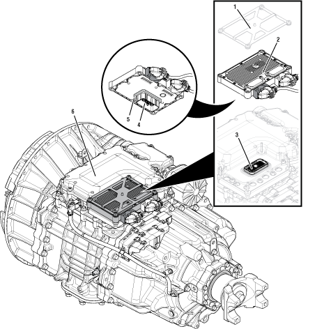 |
1. Transmission Control Module (TCM) Cover 2. Transmission Control Module (TCM) 3. 74-Way Transmission Harness Connector (MTM-side) 4. 74-Way Transmission Harness Connector (TCM-side) 5. Transmission Control Module (TCM) Seal 6. Mechatronic Transmission Module (MTM) |
Fault Code 596 Troubleshooting
Set vehicle parking brake and chock wheels.
Record the transmission fault codes, FMIs, occurrences, and timestamps from the Service Activity report created during the Diagnostic Procedure.
If Fault Code 596 FMI 0, 1, 3, 4, 6, 8, 16, 18 is Active or Inactive, Go to Step B
If Fault Code 596 FMI 5 and all the following fault codes are Active:
- Fault Code 200 FMI 14
- Fault Code 275 FMI 5
- Fault Code 295 FMI 8
- Fault Code 315 FMI 8
- Fault Code 320 FMI 8
Go to Configure Mechatronic Transmission Module (MTM) Type. Go to Step V
If Fault Code 596 FMI 5 is Active or Inactive, Go to Step B
If Fault Code 596 FMI 12 is Active or Inactive, Contact Eaton Cummins Automated Transmission Technologies for further diagnostic instructions. For Help Line phone numbers, go to Contact Information. Go to Step V
If Fault Code 596 FMI 7, 31 is Active or Inactive, go to TAIB-1006 MTM Solenoid Fault Codes and Vehicle Air System Contamination.
If Fault Code 596 FMI 17 is Active or Inactive, contact Eaton Cummins Automated Transmission Technologies for further diagnostic instructions. For Help Line phone numbers, go to Contact Information. Go to Step V
NOTICE: Refer to Vehicle Maintenance Recommendations regarding vehicle air system requirements to ensure proper air supply and air quality.
Key off.
Remove the TCM from the MTM with the 20-Way TCM Vehicle Harness Connector and 20-Way TCM Body Harness Connector connected.

Inspect the TCM side of the 74-Way Transmission Harness Connector, verify the connector is free from contamination and corrosion; the terminals are not bent, spread or loose; and there is no damage to the connector body.
Inspect the TCM Seal, verify the seal is properly installed and not damaged.
If contamination or damage is found to the TCM side of the 74-Way Transmission Harness Connector, replace the Transmission Control Module (TCM) and Mechatronic Transmission Module (MTM). Go to Step V
Note: MTM removal and installation requires the transmission to be removed from the vehicle. Reference Endurant HD Service Manual TRSM0950, Transmission Removal Service Procedure.
If no contamination or damage is found, Go to Step C
Key on with engine off.
Connect ServiceRanger.
Go To “Configuration”.
Select “Advanced”.
Note: If “Advanced” is not indicated, TCM software is unable to determine MTM Type. Go to Step 6.
Record “MTM Type” Current Value, go to Step 7.
Locate MTM part information tag and record MTM Part Number (Item 1) in table.
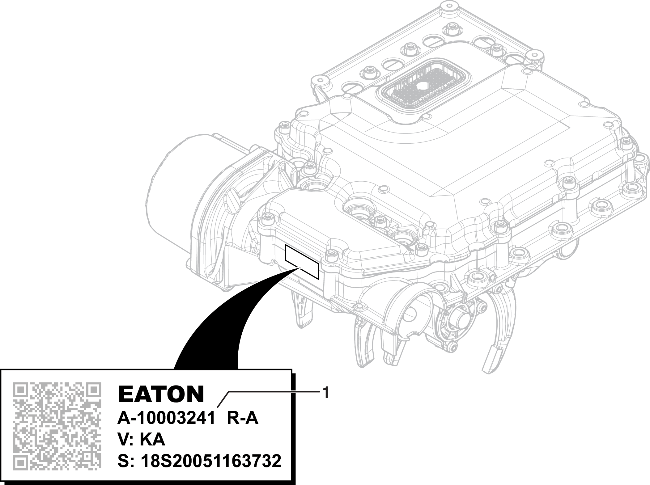
Compare MTM Part Number recorded in Step 6 with MTM Part Number in table to determine MTM Type.
If MTM Type is PS-393, Go to Step D
If MTM Type is PS-496, Go to Step E
| MTM Part Number on tag | |
|---|---|
| MTM Part Number | MTM Type |
| A-10000715 | PS-393 |
| A-10002594 | |
| A-10004202 | |
| A-10004231 | PS-496 |
| A-10004356 | |
| A-10004383 | |
Key off.
Connect the Eaton Breakout Box with 74-Way Eaton Diagnostic Adapter to the MTM side of the 74-Way Transmission Harness Connector.
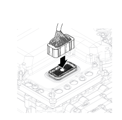
Measure resistance at the Eaton Breakout Box between Pin 50 and Pin 51. Record reading in table.

Measure resistance at the Eaton Breakout Box between Pin 50 and Ground (TCM mounting stud). Record reading in table.

Compare reading(s) in table.
If readings are in range, Go to Step F
If readings are out of range, replace the Mechatronic Transmission Module (MTM). Go to Step V
Note: MTM removal and installation requires the transmission to be removed from the vehicle. Reference Endurant HD Service Manual TRSM0950, Transmission Removal Service Procedure.
| Pins | Range | Reading(s) |
|---|---|---|
| 50 to 51 | 3.6–4.4 Ohms | |
| 50 to ground (TCM mounting stud) | Open Circuit (OL) |
Key off.
Connect the Eaton Breakout Box with 74-Way Eaton Diagnostic Adapter to the MTM side of the 74-Way Transmission Harness Connector.

Measure resistance at the Eaton Breakout Box between Pin 3 and Pin 4. Record reading in table.
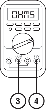
Measure resistance at the Eaton Breakout Box between Pin 3 and Ground (TCM mounting stud). Record reading in table.
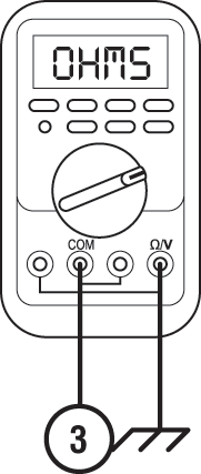
Compare reading(s) in table.
If readings are in range, Go to Step F
If readings are out of range, replace the Mechatronic Transmission Module (MTM). Go to Step V
Note: MTM removal and installation requires the transmission to be removed from the vehicle. Reference Endurant HD Service Manual TRSM0950, Transmission Removal Service Procedure.
| Pins | Range | Reading(s) |
|---|---|---|
| 3 to 4 | 3.4–5.5 Ohms | |
| 3 to ground (TCM mounting stud) | Open Circuit (OL) |
Key off.
Remove the Eaton Breakout Box 74-Way Eaton Diagnostic Adapter.
Reinstall the TCM to the MTM.
Reconnect all connectors and verify that all components are properly installed.
Key on.
Connect ServiceRanger.
Retrieve and record the transmission fault codes, FMIs, occurrences, and timestamps.
If Fault Code 596 FMI 0, 1, 3, 4, 5, 6, 8, 16, 18, 31 is Active, replace the Transmission Control Module (TCM). Go to Step V
If Fault Code 596 FMI 0, 1, 3, 4, 5, 6, 8, 16, 18, 31 is Inactive, replace the Mechatronic Transmission Module (MTM). Go to Step V
Note: MTM removal and installation requires the transmission to be removed from the vehicle. Reference Endurant HD Service Manual TRSM0950, Transmission Removal Service Procedure.
Key off.
Remove MTM.
Note: MTM removal and installation requires the transmission to be removed from the vehicle. Reference Endurant HD Service Manual TRSM0950, Transmission Removal Service Procedure.
Inspect the Primary Drive Gear for excessive fore and aft movement.
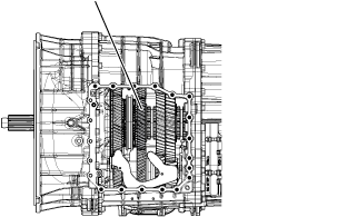
If excessive gear movement is evident, inspect the Primary Drive Gear and Main Shaft Assembly and repair. Go to Step V
If no excessive gear movement is evident, Go to Step H
Inspect the Rail B Synchronizer Sliding Sleeve yoke slot for wear.

Install the Rail B Synchronizer Engagement Tool (RR1088TR).
Note: Reference Appendix, Manually Actuate Rail B Procedure.
Shift the Rail B Synchronizer Sliding Sleeve into neutral (if necessary).
Shift the Rail B Synchronizer Sliding Sleeve into the Secondary Drive Gear engagement position (fore).
Inspect the Primary Drive Gear and synchronizer ring clutching teeth for wear.
Return the Rail B Synchronizer Sliding Sleeve to neutral.
Shift the Rail B Synchronizer Sliding Sleeve into the Primary Drive Gear engagement position (aft).
Inspect the Secondary Drive Gear and synchronizer ring clutching teeth for wear.
Return the Rail B Synchronizer Sliding Sleeve to neutral.
If the Rail B Synchronizer Sliding Sleeve shifts into all three positions and no clutching teeth wear is present, replace the Mechatronic Transmission Module (MTM). Go to Step V
If the Rail B Synchronizer Sliding Sleeve does not shift into all three positions and/or clutching teeth wear is present, reference TRSM0950 Main Shaft and Countershaft Service Procedure for replacement of the following components and Go to Step V
- Primary Drive Gear
- Rail B Synchronizer Ring
- Rail B Synchronizer Sliding Sleeve
- Rail B Synchronizer Small Parts Kit
Notice
Key off.
Reconnect all connectors and verify that all components are properly installed.
Key on with engine off.
Connect ServiceRanger.
Go to “Fault Codes”.
Select “Clear All Faults”.
Operate vehicle and attempt to reset the fault code or duplicate the previous complaint.
Check for fault codes using ServiceRanger.
If no fault codes set and the vehicle operates properly, test complete.
If Fault Code 596 sets Active during operation, Go to Step A
If a fault code other than 596 sets Active, troubleshoot per the Fault Code Isolation Procedure Index